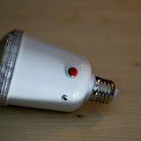
These devices are cheap and often included if you buy a light-stand or umbrella on ebay.
They have a number of problems that I am trying to solve by modifying it:
- The light-sensor can't be switched off, so this thing flashes when other prople then you try to take a photo with a flash. => I'll add a switch for that.
- You can't control the brightness. => I'm trying to come up with a way to do that. Have to talk with some people on how to do this.
- Your equaly cheap RF receiver will dangle off the side => I'm trying to include the PCB of these wireless flash triggers into the case and add a hot-shoe to the case in the process.
The PCB seems to be well labeled and the parts trivial to identify and large enough to solder.
I just need to be careful about all the traces that carry 230V.

(click to see the other photos) Looks like 130V AC is fed through diodes and a 0,2KOhm resistor (left side on this photo) labeled "200RJ" and "10 Watt" into 3x 275V 220uF capacitors. I guess replacing that giant resistor with a variable one that I can control with a knob could allow me to reduce the power in the capacitors and thus the power of the flash.
3 Kommentare:
I think the resistor you are looking at is limiting the charge current. Replacing it would just change the recharge cycle-speed.
What you want to do is limit for how long the flash is on. You could either control time with an ic or limit charge by putting switches on the capacitors so you can chose how many to use.
Try not to change the flashvoltage as that would change the light temperature.
I noticed that too after ding some reading here.
One of the 3 connected led-style parts should be a photo-diode to break the circuit at the flash-bulp side that I could replace with a variable resistor.
At least that's what others with other flashes seem to have done.
The 2 led-type elements on their board are both LEDs.
The third one is not and it's labaled "sky" on the main PCB.
Kommentar veröffentlichen