2016-12-20

Adding homing-sensor to 4th axis on CNC

  1. Next project: updated mount for Z axis homing sensor

 Purpose

I have a 4th axis on (both) my CNC milling machine(s).
I want a home switch that indicates a perfect 0°.
So I can stop a job, switch off the machine and later home all 4 axis to their homing switches, jog to the last position and continue the program.

Later I'd like to do the same for a planned 5th axis.

Status

Ordered the sensor. Not started doing it yet. Stay tuned... (this blog posting will be updated)

Hardware choices


This is my 4th axis. (50:1 harmonic drive gearbox with a K11-100mm 3 way chuck attached.)

M8 2mm sensing DC 5 V NPN LJ8A3-2-Z/BX-5V zylinder induktive näherungsschalter sensor arbeitsspannung 5VDC spezielle für MCU


This is the sensor "Finglei Electric LJ8A3-2-Z/BX-5V" (5V NPN induction sensor) I'd like to mount as a home switch.

Why inductive?

The sensor needs to not block the movement of the 4th axis past 360°.
For a simple, mechanical switch that can be solved by attaching a ramp to the disc.
However it also needs to allow movement in the opposite direction. That doesn't work well with mechanical switches.

Optical switches can get confused by dust and shavings.

So I have chosen an inductive sensor as the most reliable and simple option.

Cabling


I have taken my information from this tutorial and this discussion.

  • connect blue to GND
  • connect brown to +5V supply voltage for the sensor (I could have used a 48V sensor but I wanted to play it safe)
  • connect the remaining black wire to +5V via a 100KOhm pull-up resistor
  • and also connect the black wire to the input.
My PLCM-E3P CNC (used with the PLCM-B1 breakout board) provides me with 15 inputs to use here. They can work with 5V signals.

Note:
You can't use the +5V from the stepper-enable outputs to drive the sensor inputs.
(e.g. for a tool-height probe).
I had to add an extra 5V supply just for that existing tool-height probe.

Mechanical


My plan is to
3D print a mount for the sensor on the side of the gear box.
(Possibly using the slots that already mount the gear box to the table to not accidentally drill into the gears inside)

Then attach a modified wascher to one of the bolts securing the chuck to the plate to detect when it passes the sensor once every 360°


The sensor must have a gap of no more then 2mm to it's metal target.
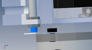
Update: In  MK2 I forgot to leave clearance for the heads of the M6x30 machine bolts. So I had to change the design slightly for MK3.


Here is the 3d printable design of the sensor holder:

2016-12-12

Multi Axis G-Code generation with CNC-Toolkit

Yes, CNC-tookit is ancient. But since Fusion 360 doesn't do the job...so well...
Here are my notes about how to get cnc-tookit running on a modern Windows 10 and create 4 and 5 axis toolpathes with it.

I may add screenshots to illustrate my notes at a later point.

Objective

I'm trying to figure out if and how to generate 4 and 5 axis G-Code in CNC-Toolkit to run on my heavily modified YooCNC 6040 machine.

Getting the software

  1. get GMax
  2. get CNC-Toolkit
  3. The registration website for the (always free) GMax software no longer exists... GMax registration workaround 
  4. I haven't looked at these yet  

Setting up Gmax

Before you start, you should select the system unit of meassurement in Gmax using Customize-Preferences... and then General-System Unit Scale.


Geometric assumptions

Some assumptions I do about the CNC machine:
  • We use a 4 axis machine with the A axis mounted on the bed of a carthesian CNC mill.
  • The A axis is running along the X axis (along Y it would be the B axis after all)
  • The center of rotation is at Y=0 Z=0
  • The stock starts at X=0 and ends at X>0
  • The stock is cylindrical. 
  • positive Z mean "up" from the center of rotation towards the spindle.
Further assumptions:
  • We use a ball nose cutter
  • We are only interested in FINISH-passes. (For roughing 3 axis milling of X+A+Z is enough)
  • STL-file and tool sizes and machine coordinates are in millimeter

From STL to G-Code 

I used this tutorial to make these notes.

  1. Make sure your object is already scaled to the right size.
  2. Orient your object along the Y axis.

Convert STL to 3DS

GMax doesn't seem to understand STL or the unual CAD file formats.
So we need a converter.

3D Exploration 1.5 can be found here : cnczone.com/forums/attachment.php?...
(Yes, you need a user account in the CNCZone forum.)
In Windows 10 you need to install this using compatiility settings.
It is discontinued but you should of cause still register it for 40.77 € +19% sales tax = 48.52 €.

If objects in the original file exceed the 64,000 faces per object limit for .3DS, it splits info face groups that you need to reunite inside Gmax using the Editable Mesh 'Attach' or 'Attach List function.

  1. Open "3D Exploration 1.5".
  2. Select your file on the right side.
  3. Select File-Save As... and the 3ds file format.

combine face groups

On the right side you have  a number of tabs,
  1. In the first tab, you can assign a name to your objects to identify them.
  2. In the "view" tab with the monitor icon, you can hide objects that clutter your view and render them as solid objects.
  3. In the tools tab, you can "attach" and "attach list" multiple face groups into a single mesh.

Load model

  1. File-Import your convertes mesh.
  2. Make sure it's oriented along the X axis due to limitations of cnc-toolkit.
  3. Note down the size of your stock.
  4. Select your object and in the top right panel, give it a name.

Run cnc-toolkit

  1. Run the "CNC-Toolkit-4.34b.ms" MaxScript file using the menu.

Next select your machine type.
  • XYZ is a 3 axis mill
  • XYZA has 
    • a 4th axis mounted on the work-surface that rotates around X
  • XYZAB has 
    • a 4th axis mounted on the work-surface that rotates around X and
    • an additional 5th axis "B" mounted on the Y gantry, rotating the spindle around Y
  • XYZABC has a trunnion arm mounted on the Y gantry
    • C mounted on the trunnion rotating around the vertical axis
    • B mounted on the C axis to rotate perpendular to to C
  • XYZAC has a 4th and 5th axis combination mounted on the work surface. 
    • A rotating the table and 
    • B rotating the part on the table surface
The offsets are the distance from center of rotation to the tip of the tool.
For an axis mounted to the work table,  as with XYZA and XYZAC I assume it's the distance from center of rotation to the origin point.

Create a cylinder of splines

  1. In the "parallel splines" section choose "helical" or "cylindrical"
  2. Enter apropriate X, Y and Radio -dimensions for your stock.
  3. Click "Make parallel splines" and wait a second for them to apear.
  • "Stepover Distance" controls the distance of parallel toolpathes at the outher diameter.(Oviously the closer they are to the center, the closer they get. Keep that in mind for stock that can melt or catch fire.)
  • Despite the name "Stepover" is an absolute distance between tool passes and ignoring the tool diameter.
  • "Stepover" also ignores any changes in radius during the later projection. As the spline gets near the center of rotation during projection, the resulting toolpathes are much closer then the initial "Stepover" distance.

Project splines onto surface

  1. In the "project spline" section, click "object" and select your object.
  2. Select the spline.
  3. Click "project around X axis"
  4. Delete the unprojected spline using edit-delete (it's no longer needed and can be re-created with just 1 button)
It should now wrap the surface of your object.
  • Height offset is otherwise known as a skin depth and allows for roughing passes

Create tool vectors along projected spline

  1. Up in the "angle control" section, choose "Use Reference Surface".
  2. Then "Pick Reference Surface".
  3. Select your object and the button should not read "Ref Mesh = ". 
  4. Select the projected spline. (Not the original spline. You can delete that one.)
  5. In the "toolpath generator" section, choose "Toolpath from Shape".
You may have to wait for a few seconds.

Generate g-code and show animation


Now you can use the "Tool Control" and "Postprocessor Options" sections to export your g-code to the "Script listener window" to copy and paste it.
(The other options here work in 3D Studio MAX but not in GMAX)

You can find that windows with F11 or in "MaxScript"- "MAXScript Listener..." .

After postprocessing, you can use "/" or the play-button in the lower right to see an animation of the milling process.

TODO

I have not yet fully understood how to compensate for the tool shape.
The tangent mode seems to use the entered tool diameter and offset it along the surface normal.
This simple method would of cause be problematic in pockets narrower then  1.0x the tool diameter that can not be milled with a tool of this size. However an infinitely small tool will try and the applied offset will cut widen the pocket beyond the intended geometry.

As an alternative I should test importing an existing 3 axis toolpath and having cnc-toolkit perform the too-orientation only. Aparently toolpathes from CamBam (trial versions) can be exported as DXF and imported into GMAX. I don't think that works for gcode -toolpathes of my favorite 3 axis CAM software.

I have also not understood yet how to use your own geometry to represent your machine for better visualision and for collision detection. Aparently you can "link" your own geometry to follow the path of the generated stand-ins and then hide the stand-ins.

2016-12-11

Multi Axis G-Code generation with Fusion 360


Objective

I'm trying to figure out if and how to generate 4 and 5 axis G-Code in Fusion 360 (Hobbyist version = ultimate features) to run in MACH3 on my modified YOOCNC 6040 machine.
Why?
Because even the new "5 axis operations" in Fusion 360 don't work for organic shapes without contours. Any I only ever need/want 4 and 5 axis milling for organic shapes to get perfect surface finish on curved surfaces.

Status

This is a WORK IN PROGRESS and I'm using this blog posting to collect the links and bits and pieces I found so far.

Machine compatibility

I could not yet determine if the machine control program (in my case MACH3) is required to support TCP (tool center point) compensation.
This means that X+Y+Z coordinates in G-Code refer to the center of the tip of the tool and A+B+C refer to the angle of attack.

During G-Code Generation Fusion 360 has absolutely no idea if a given orientation is mechanically impossible for the machine to perform and thus cannot aproximate it with a less then ideal angle of attack or a similar mitigation strategy.

It is clear that all calculations happen in the Machine Configuration.
To get there you already need to have a toolpath. It's in "postprocess"->Open Config.
"Tip: Ask your reseller about customization of the setup sheets and post proces" is not very helpful if you build the machine yourself and therefore ARE the "reseller".

Milling Strategies 

There is no German documentation yet.

Trying OpenBuilds linear actuators with end stops


I'm trying out expensive but (up to this step) well done OpenBuilds kits combined with cheap 20x20 I-Type aluminium profiles for a machine I'm building.

However uppon installing the OpenBuilds End-Stop kits I just got a big WTF moment....
(Images directly from the OpenBuilds Part Store website. So nobody can claim the photographer got it wrong...)


1) How the *** am I supposed to attach a micro switch to an aluminium plate like this? There is no thread for the screw to fasten to. It's just 2 oversized holes in the mounting plate. Inserting the screws liks shown just means to loosely stick them in there and want for them to simply fall out on their own.


No you can't insert them the other way around because these are not sink hole screws with tappered holes in the aluminium plate. So you don't get a flush surface to mount this crap to the aluminium profile rail.

2) Why is +Open Builds requiring a different tool-size (1mm hex) for "Micro Limit Switch Kit with Mounting Plate" then the 3 different tool sizes they already need for the "V-Slot™ Linear Actuator Bundle" (1.5mm, 2mm and a tiny one for the stepper)?

3) Why no use a smaller screw that fits THROUGH the holes in the micro switch instead of eating their own thread into the plastic.

2016-10-06

Lenovo and UPS completely FAIL to deliver my new Laptop


On 30.8.2016 I ordered my new Lenovo P70.
A 4400eur workhorse of a workstation-laptop that was supposed to accompany me for the next 5 years to come.

On 3.09.2016 my payment was acknowledged.
...so far so good.
Somehow on the same day I was asked to register within 30 days for my 5 year extended waranty. Despite obviously not having a laptop for weeks to come. However after a quick email I was told that I only needed to register after actually receiving the laptop.

On 10.9.2016 I got a strange notification that I was shipped???? a 5 year waranty. However that is physically possible.

On 14.9.2016 I was informed that my laptop was delayed and would be shipped on 27/09/2016 (+1 week).

On 22.9.2016 I was informed that my laptop was delayed and would be shipped on 20/10/2016 (+1 month).
However 2 days later I was already informed that my hardware had been shipped. However
  • with an empty tracking number
  • no mention what shipping service was used
  • login data for a broken shop system that doesn't allow me to see or do anything at all despite look at the same error code in Firefox, Chrome and Safari on MacOS, Windows and Android.
On 27.9.2016 I finally got an answer that of all the possible shipping companies, Lenovo in their infinite wisdom had chosen UPS. ...and a tracking number.  ...that's when the "fun" starts.
I never ever choose UPS for anything. It's not a regular parcel service. It's a business 2 business curier and as such ONLY works for delivering to businesses that have offices that are open every weekday 9-5. They are completely incapable of delivering to a private address of anyone who works during the day. They don't have offices, robotic parcel-pickup stations or a way of deliverting to dropoff points or other neibours. They never invested in any of that because business 2 business couriers don't need that.

I don't work in the same city Mo-Fr where I live Sa+So. The city where I work changes frequently.

UPS answered that
  • I can not pick up my order on a Saturday because they are closed.
  • I can not reroute my package while it is still in Cologne (there it was scanned again and again for 4 days straight. 4-5 times a day. Without going anywhere.)
  • Lenovo has explicitely forbidden them from rerouting the package to my workplace and that was only possible after the first delivery-attempty anyway-.
  • They are incapable of routing the laptop to the only UPS partner shop for pickup.
  • They never invested in their own Packstation -network.
  • They are incapable of drop-shipping into my shed behind a code lock.
Lenovo answered that
  • They can not change the delivery address after it was shipped. (Not understanding that this wasn't what I asked. I asked Lenovo to simply allow UPS to change the address.)

On 6.10.2016 I just received a message that I have registred for my 5 year waranty....despite never having done that because I never received a laptop yet.
I have moved heaven and earth to find a way to stop work very, very early and take 3 trains, 1 taxi and 1 car ride to get to the depot 30min before it closes (according to the website).... only to be informed on telephone that the depot has changed it's opening hours and will close way before I have any chance of getting there.

So on 7.10.2016 my laptop will  be automatically returned to China.
...Levono said they would refund all of it. (I hope that covers the paid for exended warranty.)

2016-08-28

Multicam editing in DaVinci Resolve 12.5

One of the great new features of Davinci Resolve 12 is multicam editing including synchronizing cameras via their sound track.
Something I have done extensively in Final Cut Pro X and now want to do directly in Resolve, so save the extra step of colour graded, intermediate files rendered from Resolve and edited in FCPX.

Since nobody seems to write about actually using this feature, I use this blog posting to document my findings.


Summary

If you don't want to read all of it:
  • you can't add a camera angle to an existing muticam clip with automatic syncing
  • syncing by soundtrack doesn't work at all (either crashes even in trivial cases or doesn't sync) 
  • there are serious bugs and even crashes related to multicam clips.
  • file creation dates can not be used as a criteria to get at least a starting point
  • identifying what clips are from the same camera doesn't work (ignored Camera ID metadata field)

Setup

Software:
Davinci Resolve 12.5 Studio with hardware dongle on MacOS.

Show:
This is a stage show. Not scenic film. Not a documentary.
Together with sports events this is probably the most common occurence of a multicam edit of more then 3 cameras. (Interview typically max out at 3 cameras.)

Material to work with:
  • No clapperboard (the audience wouldn't be pleased) 
  • No time code synced via cable (hald the cameras don't support it, TC-generators cost a fortune and we aren't allowed to put cables all across the emergency exit routes)
  • Nothing can ever be re-shot. There is one chance and one chance only to record it.
  • 1 Zoom H6 doing a continous audio recording (including -6dB backup) including pause times.
  • 2 Blackmagic Pocket cameras in ProRes with Atomos Samurai Blade HDD recorders
  • 2 GH4 with Atomos Shogun SDD recorders
  • 1 Blackmagic Production Camera 4K recording RAW (for dark scenes for easier denoising) and ProRes (for bright scenes to save SSD space due to limited number of SSD we could rent)
  • 1 GH4 with internal MPEG recording
  • some 3rd party footage will come in later
  • cameras record 3 acts of 4 scenes per act but not the pause times

Problems identified

Problems in Ingestion

  • Resolve doesn't import any camera name/id from any camera except the Blackmagic Production Camera 4K in RAW (but NOT in ProRes) => WTF?
  • Individual dropped frames in RAW recordings (it's a 3+h show. Such things happen) have to be manually added via shell-script for Resolve to even acknowledge that there IS a recoding in that directory and not a million image files. => not exactly robust software for a production environment

Problems in automatic syncing

Due to the 2GB limit, the audio track is broken up into 3 files.
  • syncing even a single clip to a compound clip of the 3 arranged audio files crashes resolve every single time => Bug ticket with Blackmagic Design [Support #BAX-398-79379]
  • syncing to the 3 individual wave files lets everything start at 0, even the 3 audio files with file creation timestamps indicating their correct positio (*hint* *hint*)
  • Same for any atempt to sync 2 video clips with 95% identical audio 
  • "detect clips from same camera using: Metadata Camera #" completely ignores any manually entered value into the "Camera ID" metadata field => BROKEN
  • There is no way to define a track as the master track for every other track to sync against
  • There is no user interface to ADD an additional camera/clip to an existing multicam clip with automatic syncing.
  • There is no user interface to re-sync a single or multiple, selected clips inside a multicam clip.
  • There is no user interface to even create a new multicam clip from clips that are in different bins (e.g. because you like to organize clips by camera to make colour grading them easier)
Result: syncing via audio track IS BROKEN and the feature is HIGHLY INCOMPLETE.

No software should EVER crash (at worst it should display an error message) and this feature plain doesn't work even under ideal real-world conditions. Maybe it would work if the cameras had identical audio tracks instead of recording the same audio independently using their own microphones but that's not a realistic scenario nor a useful feature.
Without the ability to add tracks later, the implemantation of this feature can not be considered to be "complete" in any sense of the word. 

Problems in manual syncing

  • Draging a new video clip into the audio area of a multicam adds only the audio.
  • The selection of what should be visible and non-silent when doing sync-work in the multicam clip directly affects what video and audio angles are exported for use in timelines that make use of this multicam clip. Anything you hide/mute will not be offered as a choice later or display as black/silent.
  • There is no way to scale the waveform display without adjusting the audio levels, so that you can clearly see all you need to see for manual syncing via audio waveforms.
  • There is no visual display of the border between individual frames whe zoomed in far enough in manual syncing. You only notice how far you have zoomed in when trying to move the clip around.

Problems in workflow

  • Clicking or double clicking a multicam clip or timeline does not open it in the timeline editor...it simply does nothing at all. 
  • When doing picture-in-picture and multicam clip that makes up the smaller picture has no clip for the selected angle at the current time, not only does the scaled-down area where the PiP would apear go black but the ENTIRE frame goes black. => Bug ticket with Blackmagic Design [Support #BSX-823-55972]
  • The manual refers to keyboard shortcuts as they are on an English keyboard. There doesn't seem to be a German manual explaining the German keyboard shortcuts. (Something like "Option-Shift-[" or "Option-Shift-\" would break your fingers as "[" and "\" are Option-combinations of digit keys and not first order keys here.)
This blog posting is constantly being updated while I am editing my multicam project.

Links   

2016-06-27

Getting started with the Raspberry Pi 3 OctoPrint Bundle


After upgrading to the low friction spool holder,
I just got myself the Raspberry Pi 3 OctoPrint Bundle from Watterott.
It shall be the center component of my Ultimate Filament sensor.

Since it doesn't come with any instructions, here is what you need to do:

Setup


Don't plug it in yet!
Insert the SD card into a regular computer and edit the file octopi-network.txt .


Then insert the 2 transparent elements into the 2 holes near the micro USB socket.
(Yes, there are 2 plugs for 4 holes and no instructions.)


Now insert the Raspberry Pi and then insert the SD card.
The contacts should face upwards.
(It is near impossible to the the cards out again.)

After switching it on, you can connect to it via http://octopi.local .

SSH

You can also access the raspberry via SSH
ssh pi@octopi.local
The default password is "raspberry.
The SD card is mounted as /boot
The OctoPrint config file is at "/home/pi/.octoprint/config.yaml"
You can restart the server via "sudo /etc/init.d/octoprint restart"

If your Wifi access point via
sudo sudo iwlist wlan0 scanning | grep ESSID
can't be seen by Linux, run
sudo raspi-config 
and select "5 internationalization options" -> "I4 select Wifi locale"
to enable the Raspberry to see all Wifi channels that are legal in your country.

The Raspian I got was very old. I had to provide Internet via Ethernet and do
sudo apt-get update
sudo apt-get dist-upgrade
then it was able to see Wifi networks on Channel 40 (5GHz) and 12+13 (2.4GHz).

GPIO fun 

While at the shell, you can have fun with the GPIO pins in Bash.
Sadly you can't set the pull-up resistors from the shell.
However my image came with WiringPi already installed.
It doesn't have a "--help" or a man page on the Pi itself, so here are the basics:
  • gpio readall
  • gpio mode (pin) in/out
  • gpio mode (pin) up/down/tri         (set pull up resistors)
  • gpio read (pin)
  • gpio write (pin) 0/1
  • gpio wfi (pin) rising/falling/both    (non-busy waiting for a state change)
  • (more)
  • (reading multiple gpios )
  • ...including timeout via read -t (seconds) || echo "timeout detected"  ...still in bash ;) 

Camera


Sorry, there is no hole for the Raspberry Pi camera. The best place to cut one is probably on the side (so you don't damage the cool logo), above the camera connector.

This longer cable (Reichelt) may be helpful.

Cura slicing

Luckily the Bundle comes with thje CuraEngine plugin preinstalled. So slicing it not much of a problem.You can imort your existing 15.x profiles (but not 2.1.1 profiles) in Settings->Plugins->CuraEngine->import profile.

BTW, there are "send to Octoprint" plugins for Cura on the desktop!

Ultimaker II setup

The Ultimaker series is not supported out of the box.

Settings->printer profile:

Profile  (UM2 extended)

  • Color: default
  • (X) Rectangular 
  • Origin: lower left
  • X: 223mm
  • Y: 223mm
  • Z: 315mm
  • (X) heated bed

Profile  (UM2 go)

  • Color: default
  • (X) Rectangular 
  • Origin: lower left
  • X: 120mm
  • Y: 120mm
  • Z: 115mm
  • (X) heated bed

Profile  (UM2)

  • Color: default
  • (X) Rectangular 
  • Origin: lower left
  • X: 223mm
  • Y: 223mm
  • Z: 205mm
  • (X) heated bed

 G-Code

After "after abort of a print job" enter:
;fans off
M107
;extruder heater off
M104 S0
;heated bed heater off (if you have it)
M140 S0
;metric values
G21
;absolute positioning
G90
;move Z and X/Y to min endstops
G28 Z0 X0 Y0
;relative positioning
G91
;retract the filament
G1 E-5 F300
;steppers off
M84
;absolute positioning
G90


Cura 15

in Cura set: GCode Type = RepRap (Marlin/Sprinter)
start.gcode (first line must be blank)

;Sliced at: {day} {date} {time}
;Basic settings: Layer height: {layer_height} Walls: {wall_thickness} Fill: {fill_density}
;Print time: {print_time}
;Filament used: {filament_amount}m {filament_weight}g
;Filament cost: {filament_cost}
;M190 S{print_bed_temperature} ;Uncomment to add your own bed temperature line
;M109 S{print_temperature} ;Uncomment to add your own temperature line
G21        ;metric values
G90        ;absolute positioning
M82        ;set extruder to absolute mode
M107       ;start with the fan off
G28 X0 Y0  ;move X/Y to min endstops
G28 Z0     ;move Z to min endstops
G0 X20 Y20 F{travel_speed} ;bring extruder to the front
G1 Z25.0 F{travel_speed} ;move the platform down 25mm
G92 E0                  ;zero the extruded length
G1 F200 E25              ;extrude 25mm of feed stock
G92 E0                  ;zero the extruded length again
G1 F{travel_speed}
;Put printing message on LCD screen
M117 Printing...
end.gcode (first line must be blank)
;End GCode
M107 ;fans off
M104 S0                     ;extruder heater off
M140 S0                     ;heated bed heater off (if you have it)
G21 ;metric values
G90 ;absolute positioning
G28 Z0 X0 Y0 ;move Z and  X/Y to min endstops
G91                                    ;relative positioning
G1 E-15 F300 ;retract the filament
M84                         ;steppers off
G90                         ;absolute positioning
;{profile_string}

Cura 2.1


The documentation should be here However that's not the whole picture incomplete.
You need an Ultimaker2extended, Ultimaker2Go or Ultimaker2 profile with the reprap g-code flavor to have start and end added to your gcode files including material temperatures, homing and shutdown. Like this one.
To avoid adding files to Cura itself (and keeping them after updating Cura),
you can put your .json files for a new machine definition here:
  • Cura 2.1 (Linux) ~/.local/share/cura/machines
  • Cura 2.2 (Linux) ~/.local/share/cura/definitions 
  • Cura 2.1 (OSX) ~/.cura/machines for 2.1 or ~/Library/Application Support/cura/definitions
  • Cura 2.1 (Windows) ~/AppData/Local/cura/machines
  • Cura 2.2 (Windows) ~/AppData/Local/cura/definitions for 2.2 
Due to bug #850, you need to copy the fdmprinter.json, Ultimaker2.json and other files you inherit from into the same directory.

You can also add additional materials (use the existing materials in Cura 2.1.2.app/Contents/Resources/cura/resources/profiles/materials as a reference) to
~/.cura/profiles/materials (OSX)
but be careful, the file structure is identical to the MATERIALS.txt that the firmware imports from an SD card but the property and section names inside are different. Strange design decision.

Ultimaker II attachment

mechanical

It looks like self adhesive Velcro is the best option to attach the box to the back of your Ultimaker II.

Electrical


Having a Raspberry Pi permanently connected to your printer, that has ample 5V and 12V, it is kind of silly to power it via a separate wall wart. So we should see about powering it from the Ultimaker.

Settings

g-code for "after pause"
G91 ;relative positioning
G1 E-25 F200 ;retract the filament before lifting the nozzle, to release some of the pressure
G1 Z20 F15000 ;move the platform down 20mm
G90 ;absolute positioning
G0 X20 Y20 ;bring extruder to the front
g-code for "resume after pause":
G91 ;relative positioning
G92 E0 ;zero the extruded length
G1 F200 E55 ;extrude 55mm of feed stock
G92 E0 ;zero the extruded length again
G1 Z-20 F15000 ;move the platform up 20mm again
G90  ;back to absolute positioning
G1 F600 ; set travel speed

Links:

2016-06-20

Ultimaker II upgrade with Low Friction Spool-Holder


I'm currently upgrading my Ultimaker II with a "Low friction UM2 spoolholder" the YouMagine user IRobertI.

As I print a lot, I use huge and heavy Colorfabb 2.2Kg spools.
So when a spool is fresh and heavy, there is a lot of friction involved that the extruder needs to overcome.
My hope is to reduce this friction a great deal with this simple upgrade.

Notes:   
  • Print "608 mount" ith lots of infill, a large nozzle and thick layers. It needs to be strong.
  • M8x140 is plenty of length. It should have a hex head, so you only need 2 M8 nuts
  • You can use counter nuts (4 in total), so the nuts stay in place even with lots of vibration over a long time period
  • Use a bolt that has threads all the way (no smooth shaf and only threads at the tip)
  • Clean up the inside of "608 Core2 90mm" and "core 1", so a 608 bearing can be inserted into the far end
  • check the order of assembly:
  1. insert M8x100 hex headed bolt into "608 mount
  2. add M8 nut and 608 (skateboard) bearing, so "core 1" has a small air-gap wi "608 mount"
  3. add "core 1"
  4. add spacer
  5. add another 608 bearing and M8 nut (don't overrighten)
  6. add "608 Core2 90mm"
  7. add final "608 nut"


2016-06-18

Panasonic YAGH for GH4 disassembly

Project

I received a broken Panasonic YAGH unit for a GH4/GH4R camera.
The description was that it simply failed at some point and was dead. The original owner has a second YAGH in operation, so I'm ruling out handling error.

Since the Audio part also did not work, I can rule out any ground loop or static electricity issue with the SDI ports as the cause.
If the SDI ports  are broken, I'm still left with a good XLR audio preamp for my GH4. ;)

My educated guess is a burned protection diode/0 Ohm resistor/fuse in the power supply due to a power spike or ground loop.

Disassembly

This unit is all nuts and bolts.
Don't start this disassembly unless you have
  • a LOT of table space to lay out the bolts
  • a means to print photos you made of each board/side/layer to put the bolts on
  • I learned the hard way that putting the unit onto a photocopier does NOT produce good results
You have to remove all visible screws on all sides to remove the outher plastic hull.
Use the photos I made to get a good understanding of how the different parts inside connect to disassemble them later.
You can have to disconnect the board with the 2 XLR audio connectors to physically separate "Main" and "Power" board.
You have to disconnect the front panel "SW-Audio" board from the "Main" board to to physically separate the elements
You have to remove the lower board "Main" with the SDI connectors to remove the plastic on top of the "Power" board. 

Aparently you can reconnect things in a way to run the YAGH without any case and easily reachable contacts. Just the upper side of "Main" and lower side of "POWER" are blocked because they mate to each other.

What surprised me was, that the unit actually contains an micro-HDMI to HDMI cable and a full sized HDMI socket inside!
My guess is that this is to easily replace a broken cable but then again...you need to completely disasembly EVERYTHING to reach that cable.

Power supply


The unit accepts XLR power with
  • 12V applied on Pin 4 and 
  • GND on pin 1. 
  • Pin 2+3 are not connected
  • Rated for 11-17V (1.4A at 12V) -> 16.8V D-Tap  power is fine but very near the top limit

Setup: I'm testing the unit with a DTap to XLR power adapter cable.
I could also use a lab power supply but attaching it would be difficult as the cables are very well insulated and leave no place where I could attach clamps.

Lessons learned: aparently you CAN insert a chinese D-Tap plug THE WRONG WAY without any resistance.

Found the problem? The Power board is not supplying power to any of the other board. The fuses are intact and there are no obviously burned capacitors or diodes that I could easily replace.

 SDI out


  • 1080p24/25/30 -> the same 1.5G SDI signal on all 4 outputs
  • 1080p50/60 -> the same 3G SDI signal on output 1 and 2
  • UHD at 24/2530fps or DCI 4K at 24fps ->4 FullHD segments as 1.5G SDI signals on each port
Conclusion: I can test the SDI ports using my Atomos Samurai Blade or shogun that both only have a single SDI input.

Audio board 


XLR inputs arrive in a small board "CJBB84417" with only passive componente.
They are then routed into the board "VJBB0F44" with 4 low noise amplifiers labeled "8202 304 JRC".
It also houses the Pogo pins to the large connector on the camera and a large connector to the main board.
Guesses:
My guess is, that this does all the audio pre-amp and hands these over to the camera.
It should also provide the volume level to the main board for display and get level information from the input board via the main board somehow.
All the other pins should just be routed through from the main board to the camera.
I fuether guess that if I supply this board with power and connect it to the GH4, it may work on it's own (with a fixed level value).
If the amplifiers are similar to the NJM8202, they should have a 15V power supply.

Links

2016-06-15

Ultimaker II filament sensor and remote control using Raspberry Pi


The Plan

This is still an idea, growing in my head. I don't know if or when I'll build it.

I want to attach a Raspberry Pi 3 to my Ultimaker II extended.
Obviously with Wifi and USB it will have
  • a camera, watching the print
  • a GPIO pin an Octoprint API call telling the Ultimaker to pause the print (via a tiny firmware modification)
I will replace the small, plastic filament idler pulley on the back of the maching (opposite to the extruder drive mechanism) and replace it with a ball bearing and 2 sensors
  • a trivial 2 bit rotary encoder to meassure the speed and amount of the filament and auto-pause if no filament is transported anymore
  • a load cell with a Hx711 module to tell how much pulling force is applied and auto-pause on no force = filament empty and too much force = something blocks the filament from moving
The too much force - part means it will also detect obstacles that would otherwise lead to underextrusion because filament is still being transported but way less then there should be.
  • a second load cell in the modified "Low friction UM2 spoolholder" will meassure the weight of the spool and thus tell me how much filament is left.
  • the modification is a 12-20cm arm with the load cell attached

Status

  1. DONE: Raspberry Pi with Octoprint installed
  2. DONE: Designed parts for first prototype (using only Encoder and Dummy-Load Cells)
  3. DONE: Rotary Encoder arrived
  4. DONE: Pinout specified
  5. DONE: Waiting for load cells and Hx711 from China
  6. DONE: Test rotary encoder from Raspberry PI command line
  7. DONE: Test Octoprint API from Raspberry PI command line
  8. DONE:  Convert rotary encoder values to binary positions, movements, direction and speed
  9. DONE:  Wrote a simple filament monitor script that detects stalls and reverse movement and pauses the print via the Octoprint API
  10. DONE: Test Hx711 and load cell on Raspberry PI using Python
  11. DONE: The current "pause" in the Octoprint API is dangerous for scripts. It can resume if issued twice. ->fixed in Octoprint update
  12. DONE: solder the final cables and mount things on my UM2extended
  13. DONE:  designed modified "608 mount" to weight the remaining filament.
  14. DONE:  meassuring the weight of the remaining filament works! 
  15. DONE:  Write the final software including monitoring pulling force and spool-scale
  16. TODO: Write an assembly instruction including setting up the software.


MKI
MKII

Testing rotary encoder
Testing load cell for extruder pulling force

The software

I'm using a Raspberry Pi running Octoprint as the central controller.
The original plan was to use the Octoprint API.
For the final software (Here on GitHub) I decided to write an OctoPrint plugin.
I can not only detect if filament is supposed to move at the moment and issue a pause command without hacking the firmware and dual-using one of the homing switches as an E-Stop.
I can also display information (such as remaining filament) in the OctoPrint web interface
and offer my meassurements as new values in the OctoPrint API.

The parts

New method (using Octoprint API)
Old method (using GPIO signal to pause the printer):

2016-04-18

continuous Multicam recording

I know, I have too many cameras.
What do you say. It's a hobby of mine.
But every now and then I actually use all of them... at the same time.
Lectures and events have a tendency of ending up as multicam events that need more then 20 or 40 minutes per camera and should have their highest possible quality because they simply can't be repeated. 


Surprisingly I got my hands on a used Ninja 2 on eBay.
Now I have completed my setup!
(inserts manic laughter here) 

Center

One GH4R with no internal recording limit can be powered by an Atomos Power Station and record in 4:2:2 onto a Ninja Assassin in UHD for the wide shot that also gives crispy sharp, post-stabilized, post-panned FullHD medium shots as a crop. It doesn't move or refocus and thus needs little monitoring.(for Wifi monitoring I would have to switch from 10bit down to 8bit and I won't do that)
An internal MPEG backup recording is running.
Zoom H6 does the sound as 6 wav including - 4dB  backup against clipping channels ,if not all channels are uses and has its line out run into the Ninja Assassin too. Channel 1+2  are the Mid/Side microphone because that gives perfect Mono down mix and can not have any stereo cancellations like the shotguns 3+4. 5+6 is a Rode VideoLink digital wireless channel to a Lavalier. 

Remote Right

One Blackmagic Pocket Cinema Camera on the far right. Powered from a Lanparte V-mount plate. An Atomos H2S converts the HDMI to SDI.
An internal ProRes LT backup recording is running.
It provides FullHD Closeups from the right .
The SDI cable runs to left side. 

Left

There am I with an Atomos Samurai Blade, monitoring and recording it and giving instructions via PMR radio to match my own framing.
Myself I am with another Blackmagic Pocket Cinema Camera, another Lanparte battery plate and the Ninja 2 for matching Closeups from the left side. Monitor is not as good and I have no scopes but I have my eyes and the screen of the camera.
Now we have wide shots from dead centered with any crop we desire and Closeups for dialogues from left and right.
Wenever something important is obscured from one side, we have 2 different angles to choose from.

Advantages

  • Each recording has a backup. 
  • I can see what the opposite camera is doing including focus peaking and give instructions
  • HDD (Fullhd)  and SSD (UHD) drives last forever 
  • so do the batteries 
  • audio from 3 locations +lav in case a chair chair squeaks and for a wide applause with no single shouts standing out
  • all recordings are in 10bit (or raw)  -  no banding when I pull the midtones up of down in post or pull up the shadows 
  • all recordings are in ProRes (or raw) - fine noise floor for NeatVideo to work with and no MPEG artifacts 
  • Editing off the 3 SATA drives directly with no need to copy anything

2016-04-11

GH4 und Lumix Club - Wie kriegt man die 100GB?


Mit dem V2.5 Firmware Upgrade für die GH4/GH4R soll man 100GB freien Speichersplatz bei Google Drive bekommen.
Kommt aus dieser Presse-Meldung:

http://www.presseportal.de/pm/14151/3293032
und wird auch so fleißig überall abgedruckt.

...bis man mal versucht das so zu machen.

Zitat:
"*Nutzer müssen sich zunächst im LUMIX CLUB (http://lumixclub.panasonic.net/ger/c/) registrieren, um dort den Speicherplatz für Google Drive zu erhalten und bis 30. September 2016 den Account Service aktivieren.
Eine Kurzanleitung zur LUMIX Club Registrierung ist verfügbar unter ftp://ftp.panasonic.com/camera/howto/compact_cameras_how_to_create_a_lumix_club_account_howto.html"


  1. Im Lumix Club findet sich kein "Google Drive"

  2. Einen "Account Service" gibt es dort gar nicht

  3. Auch die angegebene Kurzanleitung schwiegt sich zum "Account Service" und zu Google Drive aus.

  4. dafür aber das schon vor Jahren in Google+ aufgelöste Google Picasa
-> Der Lumix Club zeigt auf der Startseite dem Nutzer 3 Wartungsmeldungen aus dem Jahre 2014 

  5. Wird die Englische Sprach-Variante benutzt, kann für Support-Anfragen "Deutschland" nicht als Land ausgewählt werden

  6. Support-Anfragen sind auf ein Feld von nur einer Zeile und 20 Zeichen Breite beschränkt.


Wie zum Henker soll  man das machen?

2016-04-09

Film making power box MK II

As many of you know, amateur film making is a hobby of mine.
One particular topic I started to adress was having all these different battery types and their chargers for all the cameras, hdmi recorders, monitors, lights, ...
A while ago, I made a charging box. A euro-sized box with a 19" power socket strip and 2 velcro strips to hold all my chargers in place.

charging box MK II


I upgraded my charging box to twice as many power sockets.
Also there are 4 rows of velcro, to hold twice as many chargers.

I'm still waiting for a universal charger with 2x2A and independently interchangeable plates for NP-F, GH4, AA/AAA and BMPCC batteries. That one will take up additional space and an additional power socket and I was already running out of both.

proper labeling


All NP-F batteries are now labeled with their size on side add front and all chargers with their maximum current and battery type.

There is enough confusion and chaos as it is.
Simple, ubiquitous tasks like Batteries and charging should not be a part of that.
1 standard, stackable Euro-sized box, 1 power cable, 1 switch and it even has sockets to spare.
All my chargers are attached with Velcro also can be removed to use them elsewhere and exchanged for different ones.

Each camera has its box and you can see the size of the batteries just by looking into the box (front) or when it is mounted in some device (side).

Lanparte VBP- 01


Why this emphasizis on NP-F? Because that's my ONE battery standard that can power everything now.

Two Lanparte V-mount plates arrived.
With 2xNP-F to V-mount adaptors I can now power everything(5V accessories, 7.4V cameras and recorders and 12V accessories and 12-15V cameras) , from one type of battery and from mains power while charging these batteries in the Lanparte without taking them off.
AND I have the option of renting huge, expensive V-mount batteries without even having to rent an expensive charger for very, very long sessions.
(The charging and mains power is the huge advantage of the more expensive Lanparte plates.)


Future project:
Add a step-up converter into the dual NP-F to V-mount adaptors, so they also work with only 1 battery. Meaning I can replace batteries on the go. Downside is: I will loose the ability to charge the NP-F.

WARNING
The ground level on left and right side of the Lanparte is different. Some people have burned their BMPCC and BMCC HDMI ports by powering an Hdmi recorder and the camera from the same plate while they are creating a ground loop via the HDMI cable.
I GUESS using the same side (you have 12V on both sides) SHOULD be safe. 

Also the HDMI splitter in the Lanparte is incompatible with the signal a BMPCC outputs. I already knew this. 

Links

  • HDMI port on my Pocket melted!!
    http://www.bmcuser.com/showthread.php?10743-HDMI-port-on-my-Pocket-melted!!

  • Issue analysis and recommendations by David Green
    • only fiddle with the HDMI/SDI cables when both devices are OFF (the SDI/HDMI standard specifies insufficient ESD-protection against static discharge)
    • Connect HDMI/SDI first, THEN connect power
    • Make sure you are discharged when handling HDMI/SDI/SATA
    • The TRS(German: Klinke) Audio connection is safe against any ground loops.
    • These steps are against static discharge as well as against a discharge caused by different, floating ground levels on the regulators that power monitor and camera
    • Note: using 2 regulators that have a different ground level that is not isolated from each other, is a receipt for desaster.
    • Powering all devices from the same (e.g. D-Tap) output is safe because they all share the same ground level.
  • another thread about this issue
  • thread with an opned BMCC. SDI GND is connected to Power-GND.
    • analysis: source should be floating GND-levels on the different regulators in the plate to drift and thus build up a voltage different (that the ESD-protection can't handle when connecting HDMI after both devices are already under power)

+

2016-04-08

should I get a laser cutter?

Today the Kickstarter campaign for Mr. Beam II started.

Version I was a kit for 500-600eur.
That's the price of the very common Chinese laser cutter. They take a lot of reworking to make them safe and reliable and the kit takes assembly.
So it's okay and I considered and finally declined it.

The price point

Version II comes fully assembled for 1400eur on Kickstarter and +40% later.
That's a lot of money.

Why shell out so much when you can upgrade a 600eur one?

Why get a personal one when you can travel to the nearest FabLab for such a seldomly done thing? (Same thing with a lathe when I have a 4 axis mill. )

What to use it for?

Let's see...
I have a large and a portable CNC milling machine and a super reliable 3D printer.

Plywood constructions
Any (ugly) plywood T-Slot cases I can do on a mill just as well. More noise but no fumes and no 4mm depth limit.

Labels, front plates and stamps
Engraving I can do on mills as well and I'm not even limited to flat objects but can make use of the rotational axis as well.
Stamps are easier to on a laser but that's a very seldom use.
Front plates need  deep cuts in addition to labels.
Quite frankly I usually include the label, logo or QR code as an embossed part of the complex design itself instead of labeling things afterwards.

T-Shirts
Vinyl cutting I can do without heating and burning the material by mounting a knife in the CNC.

In addition to that I can do all kinds of complex, non flat shapes on the 3D printer.

Conclusion

I'll rather design a mount for the 4th milling axis with a vector knife in the spindle mount = vinyl and stamp vector cutting.
... and get a second 3D printer because the first one is running near 24/7 when I'm building another Robot Arm or other machine with lots of parts.
The large CNC mill was just as expensive then the - 40% Kickstarter laser and is much more versatile. But also louder and makes more of a mess.

2016-03-30

MyPrivateDisplay

I just installed a privacy screen protector on my phone.
Since I travel a LOT, I wanted people left and right of me to not be able to see the screen.

protection


Aparently it only limits the viewing angle left and right.
So in landscape mode, it does nothin at all.

colors

Colors still less saturated and highlights are clipping. Not very good.
It's like watching an overexposed photo of your screen.

touch

Tough screen working...so far.

2016-03-22

Building a "uStepper Robot Arm rev. 2" during EasterHegg


The Plan (tm)

During EasterHegg in Salzburg, I want to build a "uStepper Robot Arm rev. 2".
(Sorry, Thingiverse doesn't offer a nice iFrame-Embedding as YouMagine does.)

I want to build it, as it is.  Using their assembly instructions from GitHub. Then check it out and install improvements.
Planned improvements are:
  • mounting holes for optical homing switches on the gears
  • reduce the number of different bolt sizes and ball bearings
  • Replace the uStepper with NEMA17 steppers controlled by a chain of L6470 (e.G. SparkFun AutoDriver boards) due to simpler synchronisation of multiple axes
    • 3xAutoDriver - Stepper Motor Driver (Watterott: 2x 38eur , Sparkfun 34USD) 3A, 8-45V
      • 15x 2 pin screw-on terminals with 3.1mm pitch (3xpower, 3xGND, 6xstepper coild, 3xE-Stop) "Schraubklemmen 2.54mm Pitch (2 Pin)"
      • 5-6x 2x5 2.54mm headers  (Comms-In + Comms-Out) "Wannen-Stiftleiste gerade 10 polig RM2,54"
      • 5-6x 2x3 2.54mm headers  (Meta-In + Meta-out)
        "Wannen-Stiftleiste gerade 6 polig RM2,54"
      • 2x cable for  2x5 2.54mm headers on both sides (SPI between boards)
      • 1x cable for  2x5 2.54mm headers on one sides (SPI to Arduino)
      • 3x cable for  2x3 2.54mm headers on one sides (Meta to Arduino)
    • 3xNEMA17  (Watterott: 2x16eur) 0.33A, 12V
    • any power supply 1A, 12V for testing (final power supply will be 38-40V)
  • Change the joins with to not only be press-fit into the aluminium tubes but to have a bolt running across it (into the tube, through the join and out the tube on the other side) to allow for pulling small loads upwards.
  • Change the effector mount to use a standard ISO-9409-1-50-4-6 (=4xM6 on a 50mm circle)
  • Have a hole in the center of the mount to allow for cables
 

Preparation

I know the uStepper Robot Arm is still a Work In Progress.
I hope to get the original CAD files just in time for Easterhegg, so I can design my improvements.
I did get most of the parts from their BoM:

http://www.thingiverse.com/thing:1398215#comment-834544

bearings

5x 608Z
  • standard skateboard-bearings.
  • for 8mm shafts
  • Z=closed on one side.
  • ZZ=closed on both sides or 608 = open will work too.
5x 625Z
  • for 5mm shafts(I'm missing these)
10x 624Z
  • for 4mm shafts
(I did an order of all standard bearings 3mm-8mm a while back. So I *hope* my stock has these covered.)

Nuts

20x M3
7x M4
1x M5
2x M8
(done)

Bolts

The BoM didn't specify the type of head or material for any bolts.
So I tried to stay with hexagonal headed and PH2 ones and tried to stay away from sink-hole bolts.

1x M8x40
  •  used in Fig.10 - use hexagonal head, so you can have the bolt from below and nut on top. Other flat heads mean the nut has to be at the bottom and can fall out on disassembly.
1x M8x70
  • used as main axis for the large gears
1x M5x40
  • 1x used in Fig.48
4x M4x20
  • 2x used in Fig.55
  • 1x used in Fig.56
  • 1x used in Fig.57
1x M4x30
  •  1x used in Fig.55
1x M4x35
  • 1x used in Fig.63
1x M4x55  substituted  M4x60 as 55mm was not avaliable.
  • 1x used in Fig.65
15x M3x8 substituted M3x10 counter sunk head
  • use 4x (M3x10) in Fig.29 
  • use 4x (M3x10) in Fig.31
  • use 4x (M3x10) in Fig.33
  • TODO: where to the other 3 go?
2x M3x10 substituted M3x10 
  • 2x used in Fig.25 - longer is okay. Any flat head type.
4x M3x12 substituted M3x16
  • 4x used in Fig.9 - must be 11-13mm, head must have at most 5mm diameter
7x M3x20
  • 5x used in Fig.3 - any flat head. steel brass or aluminium but even plastic bolts are okay.
  • 2x used in Fig.21 - indended maximum head diameter 5mm but larger ones work if the head is at most 3mm in height 
4x M3x30
  • 4x used in Fig.44

Washers

5x M8 OD=15,8mm
4x M5 OD=9,8mm
2x M4 OD=8.8mm
I didn't find ANY of these sizes. So I hope grabbing large and small washers for M4,M5 and M8 from my stock will do.

Spacers

1x 14m  (update: inner diameter just wider then M8 threads)
1x 7mm  (update: inner diameter just wider then M4 threads)
Didn't find any because the BoM doesn't specify what kind of spacers they talk about.
I can't find them on the image nor the instructions.

Update: found them. Fig.36 has a typo and speaks of "space" instead of "spacers". Aparently they must have an inner diameter to fit an M8 and M4 bolt loosely.

tubes

The instructions don't specify if they talk about the outher or inner diamter
and what wall thickness is expected. (Clearly as seen in figure 20 and 22, inner AND outher diameter are important.)

1x 15x300 I got 1m of 16x1mm, it seems to be a snug fit in Gears_main_arm_15mm.stl, large_joins.stl fits but is a bit loose
1x 15x220
2x 6x240  I got 1m of 6x1mm
1x 6x252

...as you can see. The pure number of DIFFERENT bolt sizes is staggering.


Progress

Done:
  • sourcing all nuts and bolts (some bolts replaced by longer versions)
  • cutting tubes to length
  • assembled the first parts. List of suggestions for improvements is growing... 
  • Written the source code that will rund this arm using G-Code to control L6470 chips.
  • Assembled the original design as far as I can without the 625Z bearings.
  • I forked the project on github to post an improved version of the parts and the manual
  •  
     
Doing :
  • Waiting for the electronics
  • manual is coming along nicely...
  • starting to design improved parts...
Notes about assembly instructions
  • name inner+outher diameter of tubes
  • name head-type of bolts
    • M8x40 is for Fig. 10, any flat head. Steel brass or aluminium
    • M3x20 is for Fig.3 and ??? any flat head. steel brass or aluminium but even plastic bolts are okay.
    • ...
  • name where longer versions of bolts are acceptable and up to what length
  • name and show all dimensions for spacers (one is for M8, the other for M5)
  • Fig.1: a 608 (no covers) would do just as well  as a 608z(cover on one side) or 608zz (covers on both sized)
  • Fig.2: prepare how? What am I supposed to do in this step? 
  • Fig.3: no comment
  • Fig.4 use M3x20. 
  • Fig.5: no comment
  • Fig.6: use a sturdy table to help press-fit the 608Z or 608ZZ skateboard bearing
  • Fig.7: "prepare" means "insert M3 nuts"
  • Fig.8:  this is "side2.stl", not "side1.stl"
  • Fig.9: use M3x12 (at most 13mm) to mount the sides to the base?
  • Fig.10: use M8x40mm
    • M8 x 40mm
  • Fig.11: add an M8 washer of 9-12mm (if not included as a feature of base.stl)
  • Fig.12: use M3x8mm(M3x10 works too) to mount the small gear to the motor-shaft
  • Fig.13: 
    • M3x10 is too short for the  NEMA17 motor but the M3x8 are the only ones we have >12pcs of ??? (same for Fig.29+31. Question asked here)
    • you may want to do this before Fig.12 because the mounted motor determines where on the shaft the gear has to be
  • Fig.14: no comment
  • Fig.15: no comment
  • Fig.16: no comment
  • Fig.17: use a sturdy table to help press-fit the 608Z or 608ZZ skateboard bearing
  • Fig.18: no comment
  • Fig.19 
    • Is this large_joint.stl ? 
    • The "main arm" the short 15mm pipe
  • Fig.20: use glue and/or a drill and an additional M3x20 with a self-locking M3 nut 
  • Fig.21: use M3x20mm
  • Fig.22: no comment
  • Fig.23: use a sturdy table to help press-fit the 608Z or 608ZZ skateboard bearing
  • Fig.24 TODO: I seem to be missing 624Z or 624ZZ bearings
  • Fig.25: use M3x10mm 
  • Fig.26: no comment
  • Fig.27: TODO: what size of washers?
  • Fig.28:
    • use M3x8mm(M3x10 works too)
    • don't forget about the M3 nut (hole is slightly larger then M3)
    • use the thinner one of the 2 small gears
  • Fig.29: use 4x M3x10mm, make use of the recess for the bolt-heads
  • Fig.30: 
    • use M3x8mm(M3x10 works too) to mount the small gear to the motor-shaft
    • use the wider one of the 2 small gears
  • Fig.31: use 4x M3x10mm, make use of the recess for the bolt-heads
  • Fig.32: this is needed because you can't reach all 4 motor-bolts with the main gear on
  • Fig.33: use 4x M3x10mm, make use of the recess for the bolt-heads
  • Fig.34: no comment 
  • Fig.35: no comment 
  •  
  • Fig.36 
    • "space" should be "spacer"
    • Spacer is 14mm long and fits around an M8 bolt
  • Fig.38 one washer between gear and side plate is plenty
  • ...
  • Fig.44: 
    • use 4x M3x30mm, bolt heat must be <4mm in diameter
    • bracket_part1.stl
    • bracket_part2.stl
  • Fig.45: nothing to do here
  • Fig.46: nothing to do here
  • Fig.47 see comment for Fig.48
  • Fig.48 why M5? It's the only 5mm bolt in the entire construction and introduces an entirely new type of ball bearing. M4 would have worked just the same. 
  • Fig.49 one washer on the bearing, the other where the bolt exits
  • Fig.50 one washer where the bolt exits
  • Fig.51 this should be a nylon locking nut or else it will shake loose. 
  • Fig.52: nothing to do here
  • Fig.53: nothing to do here
  • Fig.54: nothing to do here 
  • Fig.55 
    • use 1x M4x30 on the secondary arm joint 
    • use 2x M4x20 on the 2 rods that connect to the triangle
    • TODO: Where to put what rod-length and what side to mount to (inside/outside)
  • Fig.56
    • use 1x M4x20 on the rod that connect to the triangle
  • Fig.57: use  1x M4x20
  • Fig.58: nothing to do her
  • Fig.59: nothing to do here
  • Fig.60: no comment
  • Fig.61: nothing to do here 
  • Fig.63: use M4x35
  • Fig.64
  • Fig.65: use M4x55 (or longer) 
  • Fig.66: finished! (with the mechanical hardware)
Notes about improvements:
  • holes for bolts should have a camfer to make inserting bolts easier by having them self-align. 
    • the holes for the 608 bearings work surprisingly well without them but it would still be a good idea since not every printer produces dimensionally accurate results.
  • labeling the holes with the bolt-sizes costs nothing in 3d printing.
  • use less different bolt sizes
  • name bolt sizes in assembly steps
  • all parts are very low resolution. Lots of clearly visible polygon-edges.
  • Gears are a highly simplified design. They however do have only little backlash.
  • ...
  • base.stl
    • M3 bolt-holes too small. 3.1mm would be better. 
    • M3 nut-holes could use a camfer (any stray sterand of filament makes this harder).
    • my bolts have a 6mm wide head. The hole is 5mm. Wider heads should be supported.
    • Make M8 hole smaller to allow for M8 washer of 9-12mm to sit on bottom 608/608Z/608ZZ bearing OR include that washer as a feature of the base.stl design
  • Gears_bottom_edited_plus10.stl
    •  M3 bolt-holes too small. 3.2mm would be better (slightly larger then the hole in the side that holds the nut). 
    • nuts are inserted too deep. You can't align them after having them fall down the shaft to meet the bolt.
  • side_plate1.stl
    • is a very tight fit into base.stl
    • a tapper on the nuts that slide into base.stl coult also help.
    • holes for M3 nuts should be hexagonal and closed on one side to prevent the tiny bolt from slipping out. (This isn't laser-cutting.)
    • move the bolt that doesn't go through the bottom gear further outwards, so it can be removed without having to disassemble the bottom gear.
  • Gears_main_arm_15mm.stl
    • camfer for 3mm bolts needed. Any stray strand of filament makes this harder then it needs to be 
    • label the gear "main gear"
  • Gears_second_arm.stl
    • no tapper for M5 nuts
    • mirror the small gear to have the bolt on the inside of the machine (accessible from above). That way it won't interfere with a longer bolt in the side_plates and the side plate can be made stronger by not having the access tunnes for this bolt.
  • second_gear_arm.stl
    • no hexagonal holes for the M3 nuts. They may shake loose.
  • link.stl
    • M4 hole is too tight 
    • large hole needs camfer. Hard to inser.
    • A flat instead of round end should make push-fitting the rod with force easier
  • triangle.stl
    • M3 holes definately need a camfer
    • convert to use M4 and get rid of the 625Z bearing size in favor of only using 624Z
  • end_part3.stl
    • integrate the M4 spacer into this part
  • bracket_part1.stl
    • wider brace to allow for 16mm aluminium rods 
    • convert to use M4 and get rid of the 625Z bearing size in favor of only using 624Z
  • bracket_part2.stl
    • should have a slightly wider holt then bracket_part1.stl , so the bolt fastens properly in the plastic
    • should allow for wider bolt-heads
    • wider brace to allow for 16mm aluminium rods 
    • convert to use M4 and get rid of the 625Z bearing size in favor of only using 624Z

Software

I'm planning to use this trivial Arduino G-Code parser, throw out the Bresenham line algorithm (since we need not generate step+dir pulses ourself) to instead feed tool-coordinates into the L6470 Autodriver boards.

Result

Links