2013-09-27

The perfect multitool

I think I found the perfect multitool for me.

What I found I need are:
  • LED lamp
  • pliers
  • phillips #1 screwdriver
  • flat screwdriver
  • knife
  • sometimes a bottle opener (although Germans open bottles with just about everything...except bottle openers.)
  • wire strippers would be handy but not needed.
I like full sized multitools but they tend to stick out in an office environment, so I can't wear them all day (wich is kind of a point of having such a tool on your belt).
Instead I carry 3 tools:

The first thing I carry on my belt is a foldable and very tiny xacto-knife. Extremely tiny, extremely sharp and with a number of replacement blades inside. I think I'll keep that.
It's similar to this one except in color and name and that it comes with a tiny belt holster:


I had to ditch a small chinese tool at the airport, having forgotten to put it into the checked in luggage
(Not because of the knife...but because it had a screwdriver. Aparently airlines are afraid Germany Engineers can do just about anything given a screwdriver and duct tape.).
In San Francisco I got myself a Portland Coast  C2899.


I also carry a small 1xAAA flashlight but can't find a belt holster tiny enough for it.
The Coast was supposed to replace it because it already HAD a flashlight.
...only that it was way too weak, required a size of batteries you don't easily get in continental Europe and constantly empty because the button was accidentally pushed by just about anything in your pocket.
...and it didn't come with a belt holster.

Now I found something else.
A chinese dealer named Yuki Guan sells a RUISS RS1016A.
It doesn't show but he answered that it's also avaliable in black and it comes with a very sturdy belt holster.
It has the same, nice grip that the Portland Coast one has but the LED lamp is bigger and cannot be activated accidentally anymore.

custom XL45 pulley for 8mm D-shaped shaft


My CNC milling machine has a weak 4th axis.
I want to attach a larger stepper motor with seriously mor torque.
However that motor has a D-shaped 8mm shaft while an XL45T10 pulley always has a 6mm shaft.
I ordered a conventional one, hoping to drill it up but it was stuck in transit (damn Hermes. An envelope would have worked better.).
So I had to design a custom pulley that could me machined without a rotary axis (less of a top guard) and fits snugly onto an 8mm shaft.

In fact, I'm 3d printing a first one and plan to do the final one with a full sized top guard on the, thus fixed, 4th axis.


    2013-09-25

    Blown stepper driver

    After doing some test cuts yesterday I'm doing the first real milling on my TravelCNC today.
    I want to find out if it doesn't loose any steps now.

    First problem:
    after switching it on there was smoke any my Y-stepper driver went belly up.
    The FMD2740A stepper driver is rated  for 12-50V DC input.
    Internally they use an LM2576S-5.0 to generate 5V.
    Maximum input voltage 45V.
    ...They do not use the LM2576*HV*S-5.0 with a maximum input voltage of 60V.
    And I'm using a 48V power supply.
    ....go figure.


    Update: The chinese dealer very forthcoming and is even offering to pay for the repair (shipping to china and back to get a replacement with the same chip is expensive, time consuming and not a permanent solution).

    I now connected the Y stepper to the A channel, set MACH3 to interpret the A channel as  a linear axis and search&replaced the axis in the g-code.
    It's not cutting.....
    The operation will take 2x 1h . That should be enough to detect any lost steps. Particularly in Z.
    Touching the hand weels on the steppers there is no jittering. So it looks good.


    Update: Test was a SUCCESS. No lost steps whatsoever anymore!!! Very smooth operation for multiple hours and interrupted with shutting down the machine for a night before resuming.

    Update: My replacement FMD2740A died too. (during 30C3) Post mortem showed a bad solder joing on capacitor 1.

    Update:  2 other stepper drivers blown. Dealer "Thomas Wu" confesses they are only good up to 45V. Not 50V

    2013-09-24

    TravelCNC doing it's first cuts

    My TravelCNC reached it's most important milestone!

    The mobile CNC workshop in a custom made flightcase now has completely new electronics and made it's first cuts using it.
    It's now a usable, mobile 4 axis CNC milling machine.
    ...soon it will also be 3D printing and vector cutting.

    TODO:
    • add Basotect sound proofing
    • connect the USB control board to the spindle controller (speed in software)
    • add table legs to the top panel to use it as a collapsable work table
    • test 3D printing (ThingOMatic already disassembled, should work)
    • Replace 10A power socket with 16A version
    • add IP64 power sockets (you always need power socket in a workshop)
    • add mounting for vector knife (like drag-knife but cutting real 90° angles)


    2013-09-11

    The last honours for my Thing-o-Matic

    Looking at this blog, it must feel like I'm not doing nothing at the moment.
    This is far from the truth. Since I tried to keep things focused and have just one blog-post per project with all the infos one would need to replicate my work.

    Problem is: Where does one project and the next begin.

    Yesterday I prepared the new electronics for my TravelCNC.
    Today I gave my untrusty ThingOMatic the last honours and dismantled it.
    I'll keep the main boards, the extruder controller and the extruder stepper driver.
    However the mechanics will be that of my TravelCNC.
    Mach3 will control the CNC's motion and also give STEP+DIR pulses to the extruder stepper driver.
    The external display and keypad will help me set just the temperature while Mach3 executes the g-code. (With the extruder=E axis renamed to A.)

    One thing I noticed was that the GND cable of the extruder heater had molten it's mounting port.
    Since the extruder never had any issues with heating up or keeping hot, this doesn't seem to have had any impace. The cable never moved after all.


    Excuse the pool photos as  I didn't bring any of my cameras to this location.


    2013-07-04

    Travel CNC/3d printer/vector cutter combination


    There are people who have a travel toothbrush.
    There are people who have a travel hair dryer.
    For years I had a travel 3d printer.
    So why can't I have a travel CNC? ;)
    So why can't we have CNC mill, 4th axis, 3d printer, vector knife and resin casting and a work table in a single, mobile, quiet, clean tool?

    Here's the plan:
    1. disassembly my old, unreliable Thing-o-Matic to reuse the (non-original) toolhead and extruder controller.
    2. mount it onto a not-too-small (400x300), very quitet, 4 axis CNC milling machine
    3. make sure I can swap between CNC spindle, 3d printer and mounting the 4th axis to orient a vector knife
    4. put everything into a custom made stage box including locks, cooling-grills and properly sunk cable holes and a low enough side wall to reach the part you're working on easily
    5. sound proof the box
    6. Fit drawers for small parts, legs to make the box-lit a table, light and enough power sockets.
    7. win!
    Sounds easy enough, doesn't it?
    I have the CNC right here (awaiting a conversion to USB while converting my large CNC machine from USB to Ethernet and from 4 to 5/6 axis), ordered foam and box and am 3D printing the adapter to use the 3D printing head and all other alternative Makerbox heads I have.

    THIS BLOG POSTING GETS UPDATED REGULARLY AS THE PROJECT CONTINUES.

    Updates:
    2014-04-13
     Prepared a metal XL timing belt pulley for the 4th axis to replace the 3d printed one.
    2014-01-25
      The portal height extension is coming along nicely. Will do the drilling and thread-cutting tomorrow.
      Then it should be done. Got mail from the customs office. Maybe one of these packages are the replacement drivers. With the help of my new Makibox I can make the missing parts for 3D printing and vector cutting.
    2014-01-12
      Most of the metal-milling done to raise the portal and Z-axis by 100mm to increase the maximum diameter of parts on the 4th axis.
     Spacers for 4th axis and tailstock have been made out of wood during 30C3 to demonstrate the CNC.
    2013-12-30
      2 more stepper drivers blown during 30C3. Dealer "Thomas Wu" confesses they are only good for 45V, not the advertised 50V. (I'm using 48V)
    2013-11-20
      Tried to attach the foldable table legs and found that I made a mistake.

    2013-11-13
      I finished the sound proofing and the electrical wiring.
      All 4 axis are working again (replacement arrived).
      Waiting for some small parts to install tool height probe and E-Stop.
      Work on integrating 3d printing can resume now.

    2013-10-27
      Made molds and tried to cast my own sound proofing anchor fittings but they didn't dry in time for my weekly return from the home workshop to the city I work during the week.
      Prepared foldable table legs to make the upper part of the case into a table.
      Prepared fittings to slide the electronics panel in and out for service.
      Packed the tools needed to improve the 10A power supply cabling to 16A. (just to be way on the safe side.)
      Still waiting for my replacement Y-axis stepper driver. (3D printing and vector cutting on hold due to that.)

    2013-10-24
    Found that soundproofing needs a lot of improvement.
    Tried to upgrade to a 16A power plug...to find that the hole for the plug is too small. :(


    2013-10-22
     Parts arrived to add the electric tool height probe.
     Tailstock of 4th axis has the correct height now.
     Broke my edge-finder while testing the 4th axis.
     Still waiting for the replacement Y stepper-driver. Limping around with the A axis driver driving Y .
     Ordered a tiny vacuum cleaner to modify. It's quite difficult to clean the inside of a stage box from the top. ;)

    2013-10-21
    Need to move the 4th axis 10mm higher to have space for the longnegh NEMA23 stepper.
    Milling the required spacer to have the tailstock of the 4th axis at the same height as the collet.
     Parts arrived toupgrade from a 10A to a 16A power plug and cable and to add a power socket for manual power tools or laptop.

    2013-09-25
      Dry run of the Mach3 cncPrinter3D plugin failed but Slicr worked fine with Mach3.
      Extruder-Stepper not yet connected to receive STEP+DIR from CNC board in parallel with 4th axis
      Y-axis stepper driver went up in smokeFirst real milling using the A driver for the Y stepper.
      NO LOST STEPS ANYMORE!!!

    2013-09-24 
     First test cuts in cardboard.

    2013-09-23  mounted CNC into the flight case and mounted the wooden board with the new electronics.

    2013-09-22
      230V wiring of new electronics finished.

    2013-09-19
      cables to finish the 230V wiring arrived.

    2013-09-18
      All 4 axis working.

    2013-09-16
      new electronics working on 1 axis. Some trouble with the X driver.

    2013-09-15
      tested new Ethernet control board on large CNC, not that it's USB control board is in the TravelCNC

    2013-09-09
      preparing the new electronics. Mounting control board, power supply, ... to a new wooden board that will act as a separator inside the flight case.

    2013-09-02
      testing one of the new stepper drivers.

    2013-08-20
      vacation

    2013-08-08
      48V power supply finally arrived

    2013-08-05
      Added a ramp to load/unload it from the car.
      Will get the new 48V 400W power supply from the post office tomorrow.
      Then I can test if the new stepper drivers can drive these steppers and the USB board works.
      (no driver for Y+Z yet, only X arrived).

    2013-08-01
     I'm at OHM2013 (Village "Sandbox" of CCCfr). The case is finished. I can control the CNC3040 using the control box of the USB6040 and my USB-controller. Still have to wait for 1 power supply and 2 stepper-drivers to arrive before I can finish the control box for the 3040.

    2013-08-01
      wheels mounted (before leaving for OHM2013)

    2013-07-31
      presenting the CNC at OHM2013 (CCCfr Village)

    2013-07-23
     Got myself a cheap Dremel 4000 to drill.
     Casebuilder.com did NOT include the required drill bits as promised. A 6mm one to mount the wheels is missing and I dont' have one at hand.
     They also included both face plates for the cooling fans but only one side of the case has the hole to mount it.
     All the locks and half the face-plates have pre-drilled holes. But the other half of the faceplates has not and while at it they could have CNC drilled the holes for the rivets too in the same run.
     (They are pre-drilled in the aluminum but not the wood).

    2013-07-23
      need a faster drill, so the wood doesn't spliter. Time for OHM2013 is running out.

    2013-07-22
      got the missing drill to assemble the case. Also brought the blue control box of my YOOCNC6040 over to see if new electronics really take care of the lost steps.

    2013-07-16
      case arrived

    2013-07-11
     PROBLEM! T-slots on the CNC3040 are some odd, non-standard size.
     planned test with Ethernet/USB instead of LPT postponed.
     Basotect acoustic foam arrived.
     Stage box was shipped
     fastener material arrived
     First milling tests
     Using the supplied LPT board the 3040 looses steps in Y and Z.


    2013-07-10
     Jogging 4th axis tested and still not working now. LED doesnt glow.

    2013-07-09
     CNC working on LPT except I can't jog the 4th axis.
     PCB for convertion to Ethernet/USB arrived.
     Beefed up 4th axis tested (on CNC6040). Holding force fine now. (on Y-stepper channel)
     Waiting for the Case.

    2013-07-08
     First 3D printing test failed.
     Metal plate on Makerbot hot-end too large.
     3D printing postponed.


    2013-06-30

    Chinese 25mm f1.4 and 35mm f1.7 CCTV Lenses für Micro Four Thirds


      I found these 2 chinese lenses for $18 and $38 and wanted to give them a try.


      • C-Mount 50mm f1.4 covering a 2/3" sensor
      • C-Mount 35mm f1.7 covering a 2/3" sensor
      I'm trying to evaliate their usefulness for FullHD video recording and for 5MPx photography.
      Since they are f1.4 and f1.7, I'm comparing them to a completely unfair competition of modern high end lenses with similar apertures.


      • Panasonic/Leica 25mm f1.4
      • Voightländer 25mm f0.95
      • Voightländer 17.5mm f0.95
      My camera is a Panasonic GH2 (with hacked firmware but that doesn't change the results here).
      EX-Tele mod is not used. Aspect ratio is 16:9 . Thus the crop factor is 1.86 since it's a multi-aspect sensor and no regular  4/3 sensor.

      A normal 4/3 sensor would have 2.0 and a 16mm Blackmagic Pocket Cinema Camera 3.0 .
      These would have less of an issue with the blurry corners of these lenses made for 2/3" or 1"=3/3" sensors. We are using these lenses way outside their intended sensor size.
      • All Photos (Including other apertures. Scaled to FullHD due to Picasa quota.)

      Here are the references:
      Leica 25mm Voightländer 25mm Voightländer 17.5mm
      (All wide open at the fastest aperture)

      Panasonic/Leica 25mm f1.4

      Voightländer 25mm f0.95

      Voightländer 17.5mm f095

      Now the C-Mount 50mm wide open and fully closed.
      I know they are hard to compare since the focal lengthes put the C-Mount lenses at a disadvantage.
      On the other hand trees are known to have tons of detail at any field of view.
      C-Mount 25mm f1.4Add caption

      C-Mount 25mm f1.4 at >f10
      These photos have been scaled down to 1920x1080 FullHD since the lenses are completely unusable beyond that.
      Both lenses are extremely prone to stray light. So don't judge the contrast using these images.
      They must be used with a lens hood (no thread, must be improvised) or french flags.
      The center of the f1.4 image is somewhat usable if moving. Everything outside the center is so blurred that this only works out when it's
      • either a dream sequence or 
      • something in the center of the frame is to be shown in a very shallow depth of field anyway or
      • it's an action cam that's only visible for a short period with the viewer distracted by the action and the lens is at risk of being destroyed.
      Stopped down it gets somewhat better but why would you use this lens stopped down except to get lots of motion blur in an action sequence.

      Now the 35mm f1.7 C-Mount:

      C-Mount 35mm f1.7

       
      C-Mount 35mm f1.7 at >f10

      Same issues. Just another focal distance.
      These may yield slightly better results on a Blackmagic Pocket Cinema Camera due to the higher crop factor yet they still will be very blury outside the center.

      Both are nice toys where it's not important if they break or not since they cost next to nothing.
      For a few Euro extra you'll get some old Canon FD glass that may have purple fringing and just match the sharpness of these in the center but keep that sharpness into the edges.

      2013-06-18

      custom XL45 pulley for 8mm D-shaped shaft


      My CNC milling machine has a weak 4th axis.
      I want to attach a larger stepper motor with seriously mor torque.
      However that motor has a D-shaped 8mm shaft while an XL45T10 pulley always has a 6mm shaft.
      I ordered a conventional one, hoping to drill it up but it was stuck in transit (damn Hermes. An envelope would have worked better.).
      So I had to design a custom pulley that could me machined without a rotary axis (less of a top guard) and fits snugly onto an 8mm shaft.

      In fact, I'm 3d printing a first one and plan to do the final one with a full sized top guard on the, thus fixed, 4th axis.


      2013-06-03

      Email to Makerbot Industries support

      After this hilarious answers from Makerbot Industries to a discussion thread on Google+, I sent the following email to Makerbot Industries....let's see what the answer will be (and open our strategic popcorn reserves).
      The support-Ticket number is #121248.


      Aparently whoever manages your Google+ page is under the impression I would get actual help with any of the following questions:
      (I doubt it.)

      Device: Thing-o-Matic


      Is there any kind of support infrastructure to send in my bot in Europe to get the brownout fuses fixed,
      so the devices doesn't erase it's settings every time is stays connected via USB while powered off?
      (And a way to ship it without the extruder breaking off in transit.)


      Is there any "service kit" or similar to fix the following design failures in your after-sales suport:
      * inadequate mechanical extruder support
       (third mounting hole unused, stepper motor hangs in mid-air. Only supported by 2x M5 bolts through 5mm balsa wood with a 100mm lever for the heavy stepper to break that wood any time the bot is transported and thus shaken or even placed in a not-upright position)
      * Glued together lower parts of the "dinos" not connected strong enough for long-time usage.
      * any way to dismount the extruder for transport despite the next issue named here?
      * missing plugs on the cables to mount any of the alternative tool heads you sold without disassembling the entire machine just to swap between extruder, plastruder MKII or unicorn.
      * missing plug on the interface kit -cable.
      * missing mechanism to tighten the belt (or mount a fresh belt since they come 1-3mm too short to mount by hand and expand to be 1-3mm too long/wavy when in use.)
      * non thermoplastic replacement belts that don't expand and stay flat when heated often for long times
      * metal support tube to support the PTFE being supposed to stay cool yet being directly screwed into the hot-end, thus warming up the filament, causing it to expand and thus jam.
      (Using a dozen heat-spreaders and 2 fans to keep the effect of this design failure to a minimum at the moment. Not exactly pretty. RepMan 3.0 had a PEEK tube years before you started designing the ToM.)
      * The delrin plunger in your 6th generation extruder filament drive mechanism. (high friction, no spring, no lever. Thus shakes loose every 5 minutes and doesn't react in any way to minute changes in filament diameter. Everyone else hat this one sorted out while you where still playing with DC motors.)
      * Any official way to organise the cables in the lower "cable hell" compartment?


      as expected:

      Hi Marcus,

      Thanks for contacting MakerBot Support!

      Unfortunately, no, we do not have any official repair shops in Europe, or even in the USA, which can work on a Thing-O-Matic. We haven't sold this product in over a year, nor have any of our distributors to my knowledge, and there is at this point simply a lack of resources. For the same reasons, there is no available service kit.

      I took a look at your order, and it seems like we've got a record of some support parts being purchased back in June of 2011, but no record of your Thing-O-Matic being purchased through us. If it is the case that you purchased it through us, please provide your original order number so that I can look it up. If it is the case that you purchased it through a distributor, I'd recommend contacting that distributor to see if they have any repair parts available.

      If you have any other questions, feel free to let me know and I'll be happy to help!

      Best,

      Alex
      MakerBot Support
      Just as I expected.
      I didn' ask for any kind of repair. There's nothing broken. What's broken is the design itself.

      PS:
      I ordered via a UK distributer since that meant european consumer protection laws apply. 

      2013-06-01

      new Zoom H4n camera rig handle

      I'm currently designing a new camera rig.
      Based on the idea of the RotoRig it shall be shoulder rig and travel-jib in one unit.
       However mine shall be CNC made and feature my camera-remote handle and a new version of my Zoom H4n remote control handle.

      So I designed the new handle and prototyped it on a 3D printer during GullaschProgrammierNacht.
      Next step: verify that it fits and CNC machine it in wood.#

      I already designed the other parts for the rig but they are too big to prototype on the crappy ThingOMatic 3d printer. So I'm planning to prototype them in cheap wood and later do them in aluminum.

      Update: Added photos.


      2013-05-31

      Yongnuo YN560-II + SF18 as mains powered studio flashes

      Just modified a (Canon compatible) Yongnuo SF18 battery pack to accept mains power.
      Now I can use the cheap YN560-II flashes on mains power.
      With my older YN460-II I had to disassemble the flashes and modify them.
      With these it's enough to modify the external battery pack.
      Pro: I can pull the cable and use them on battery power without powering them off. (e. G. When the cable is in the way or I'm tripping over the cable)

      GulaschProgrammierNacht

      First day of GulaschProgrammierNacht #GPN was great.
      I took a few minor projects with me that I didn't have the time to finish in recent month.
      A small, slow going hacker meet is exactly what I need to finish them.
      Currently I'm on the train back home to take a shower and collect some missing that tools.
      My 3d printer had been resurrected.
      I hacked an IPreAmp into the 20 eur phantom power injector with additional headphone output.
      Planning to attach the larger stepper onto my 4th axis of the CNC and finish some Arduino work later.

      2013-05-23

      Investigating 5 axis CNC milling


      Motivation


      Since I have a 4 axis CNC machine and already converted the electronics to USB and am working on a 4/5/6 axis CAM program, let's investigate what would be involved to upgrade to 5 axis machining!

      Current setup


      I have a YOOCNC CNC6040 from carving-cnc.com with the 4th axis option.
      The 4th axis is very weak and nearly unusable.

      I have lisended MACH3 as  control software and am very happy with it.

       Mechanics


      Electronics


      Antonio Eduardo Martins Palmeira pointed me at the PLCM-E3P CNC Controller (For use with Mach3).
      Let's see...

      5V DC via XP9 or
      5V from USB or
      48V via Ethernet (PoE)

      Maximum frequency of STEP signals 100 kHz (my current board does 200KHz pulses)
      15 buffered CMOS(5V) inputs
      36 buffered CMOS(5V, 10mA) outputs
      6 axis
      extra status LED connectors (connect, estop, power, traffic)
      max 2500ms buffer on card in addition to max 5000ms buffer in MACH3
      logging can be enabled for debugging
      The controller does the actual step generation using it's own clock and the acceleration profile provided by MACH3.
      It also does probing and limit switches by it's own (no software=no delay)

      Stepper driver

      TODO

      2013-05-16

      Free 4+5 axis CAM software


      I got an idea and am currently implementing it.
      It's a very simple 4 (and 5) axis CAM software to generate G-Code from STL models.

      The problem


      Well,  I have an affordable 4 axis CNC milling machine. The 4th axis "A" is commonly a rotational axis along Y or X.
      But aparently all free software you can get only does 3 axis milling.
      The only affordable software I that claims to support 4 axis milling was DeskProto. A fine piece of software and using it with the 4th axis works very well but it only does 3 Axis milling using X,A,Z and keeping Y stationary.
      All "real" 4 axis software costs an arm and a leg. Any 5 axis software I could find is completely and utterly out of every hobbyists budget.

      The idea


      Now what I'm implementing won't work for every type of geometry.
      I'm trying to but there will always be cases that don't fit my algorithm.
      The idea is as follows:
      1. Run along the A axis from 0 to 360 and along the Y axis, determine the location of the surface (classic pseudo-4-axis milling up to now)
      2. Then determine the surface normal at that collision point.
      3. Now calculate the inverse kinematic required to turn the part until the surface normal of that collision point points straight up.
      4. Determine if this new orientation creates collisions of the tool with other parts of the part or the machine, is outside the movement ranges of the axis or otherwise impossible.
      5. If it is impossible or if there is a cave beneth the surface, find the start and end of the region that has this property, put a plane through these 2 points that is normal to the A axis and do classic 3 axis milling in these planes.

      Why this strategy?


      The idea of following the surface normal is that this works like cutting along a contour. You get a surface without any visible steps.

      The problems


      Dents in the surface that can only be reached from certain directions are one problem. The fallback strategy of 3 axis milling takes care of many such cases but cannot work for all cases.

      Optimizing the collision detection for finding the surface is much more difficult then in 3 axis milling since you cannot partition your model in advance to only test the triangles that actually can be below the cutter.

      I haven't yet thought of any proper algorithms to deal with the fact that the tool has a shape.
      Currently it assumes a ball cutter of diameter 0 that can cut with the side just as well as with the tip.

      The details of the collision detection of tool and collet with the part are still not clear.

      As you see, I need a lot of help with thinking about the proper algorithms, implementing them correctly and a ton of testing.


      Update: 4 axis milling with this surface-normal strategy works in the emulator! Debugging mostly done.

      2013-05-06

      "R. P. M." 3D printer with serious CNC mill


      Tim Rastall on Google+ showed me an interesting project today. This is a beta of a combined 3D printer and desktop CNC mill. Future upgrades for a 4 th axis, laser 3D scanner,… are planned.

      R.P.M. Rapid Prototyping Mill ( 3D Printer / CNC Mill )

      Context

      There have been many attempts to mount small Dremel, Proxxon and other hand tools to 3D printers for small milling jobs. Usually these suffer from the low mechanical stability of 3D printers compared to heavy CNC mills, the high runout of the mounted hand tools and the low mechanical
      strength of the axis and axis stepper motors.

      Description

      This one is different. It uses a water cooled, heavy spindle with a dedicated VFD. Just like a conventional “desktop” CNC mill. The frame looks very sturdy and employs ball screws. It looks more like portal style desktop CNC reshaped into a cube. The Z axis is done RepRap “Darwin” or BitsFromBytes “RepMan” style. On these 3D printers it is overconstrained and introduces the well known “Z wobble” because 4 cheap, threaded rods are employed that are never really parallel or straight. This design uses 4 precision ball screws. So it may work out and allow for the (for a CNC mill) very large Z travel and support the very heavy tool.

      Analysis and outlook

      I am finding a combination of 3D printing (clean, no storage of blanks), CNC milling (very high precision, diverse materials and tools) and resin casting (diverse material properties, easy small-scale production) to be one of the most interesting fields of research In hobby machines.
      As for myself this could be an ideal tool if it would employ metric parts (for easy repair) and the performance in 3D printing and in medium duty CNC milling was known. My own CNC6040 is very limited in it’s Z travel and very long and wide. This one could be small enough to be transported to Hacker meets and –conferences with a car. (Much too heavy to carry a long in a train. 70lbs=30Kg)

      2013-04-22

      Cage for BMPCC and GH2

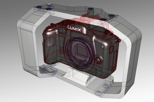
      I'm currently designing a cage for the Black Magic Pocket Cinema Camera.
      But since the camera won't be shipped before July, I'm testing my basic idea with a GH2 first.

      Let's start with the requirements:
      • small
      • follow the form of the camera
      • handheld operation, meaning I can stil grab the camera and not have to attach handles to the cage.
      • GH2: access to the battery door (not for BMPCC since it can be powered via 12V and even charge the battery while at it)
      • Access all connectors, buttons on top and the full back side.

      Mark I


      Originally I thought about a conventional design like this one and just leave a larger gab on the right side to slip my hand between camera and cage.
      The result looks like this:


       This looks nice in theory but has one important flaw.
      Because both cameras are tiny, my hand extends a significant way below the camera.

      Mark II

      So I started to look around and found this cool design.


       I liked the way it put the right side forward.
      I disliked the space below the camera as it adds bulk to the cage.

      So now I'm changing my design to put the right side forward and allow a hand to grip the camera.
      The result is this:
      Now this may be easy to grip but...it's in the way when you want to grip the lens from below to change focus or zoom.
      Turns out it is quite hard to design a cage that does not get in the way when the camera is to be used handheld, gripping the actual camera body.