2013-04-22

Cage for BMPCC and GH2

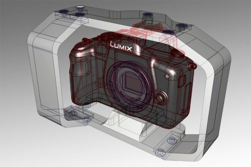
I'm currently designing a cage for the Black Magic Pocket Cinema Camera.
But since the camera won't be shipped before July, I'm testing my basic idea with a GH2 first.

Let's start with the requirements:
  • small
  • follow the form of the camera
  • handheld operation, meaning I can stil grab the camera and not have to attach handles to the cage.
  • GH2: access to the battery door (not for BMPCC since it can be powered via 12V and even charge the battery while at it)
  • Access all connectors, buttons on top and the full back side.

Mark I


Originally I thought about a conventional design like this one and just leave a larger gab on the right side to slip my hand between camera and cage.
The result looks like this:


 This looks nice in theory but has one important flaw.
Because both cameras are tiny, my hand extends a significant way below the camera.

Mark II

So I started to look around and found this cool design.


 I liked the way it put the right side forward.
I disliked the space below the camera as it adds bulk to the cage.

So now I'm changing my design to put the right side forward and allow a hand to grip the camera.
The result is this:
Now this may be easy to grip but...it's in the way when you want to grip the lens from below to change focus or zoom.
Turns out it is quite hard to design a cage that does not get in the way when the camera is to be used handheld, gripping the actual camera body.

2013-03-26

CCC Freiburg visits RaumZeitLabor Mannheim

Last weekend the CCCfr Hackspace visited the RaumZeitLabor Hackerspace in Mannheim.
Smaller then the ShackSpace in Stuttgart, we visited before, but wich much more food. ;)
We made us 3 CCCfr T-Shirts using the cool cutting plotter and shirt-press they had to offer and I found the time to drill and solder the PCB I made.
(Originally wanted to drill it on the CNC but I didn't have the right collets to mount the tiny drills.)


2013-03-22

Milling stamps

I'm currently collecting information regarding milling my own stamps on the CNC machine.
The main inspiration is to make some Hackerspace Passport -stamps for CCCfr.

Material

You can get stamp rubber easily.
I thought about deep freezing it but a friend suggested against it and to cut deep with a real sharp bit to get large shavings.

Tool

Aparently an engraving cutter seems to work fine.
Conneticut uses a 1/32"=0.8mm one FFM a 1mm one.

Speed

FFM: 16K RPM and 200mm/s
Conneticut: 6 ipm = 2.5mm/s ???? 

Depth

Both use 2 passes. 
FFM: delta-Z=-0.75mm depth=-1.5mm
Conneticut: delta-Z=0.75mm  depth=0.060" = 1.5mm


2013-03-20

My first PCB

My first (hopefully) working, etched PCB.
Made in CCCfr last night.
This time the problem was not the (stored warm and brightly lit) PCB from the store but that my acid simply cooled down.
I didn't have access to a heated machine this time, so I used a 10eur kit and hot water.
We tried to warm it up again using hot air from a distance and later a large hot water tub but it just didn't work again.
Maybe it was already saturated.


2013-03-15

Mobile Fräs-Kreissäge-Stichsäge -Tisch


Update: This project got postponed indefinitely.

Lately I've been playing a lot with my CNC and woodworking.
Gaining experience in what cutters work up to what depth, what spindle speed burns rather then cuts the wood, how fast I can go, how to mount the parts properly and what tollerances I have to calculate with due to the wood bending, vibrating and flexing.

So here is my next project:
I'm designed myself a portable table that I can mount
  1. my large circular saw (using 2 flat bars),
  2. my cheap router (using 2 round rods) and 
  3. my jigsaw (using 4 bolts).
As you can see, apart from the jigsaw, non of these tools are equipped to be mounted below a table.

Having a CNC, I'm planning not only give them
  • precise mounting points but also 
  • pocket out the shape of these tools on the underside of the table and 
  • provide a bedstop that has precise stops every 10mm, starting at 0mm from the middle of the blade/cutter. ...and use an engraving bit to 
  • actually label these stops as well as a number of distances and angles on the table
  • and label heights on the bedstop-slider (for the router)
I'm not sure I can pull this off.
For once the table is quite large compared to the working size of my CNC and I have no experience in mouting anything flat yet.
I'll have to cut provisional holes. Use these to mount it onto the CNC. Then use the precise holes to mount it while cleaning up the provisional holes.
I'll also have to think about a sacrificial plate below this part, so I don't hit the CNC's bed when drilling all the way through.
I'll also have to have an easy to center on origin location in case MACH3 crashes, takes the current coordinates with it and I have to find my origin again to resume the program.
     
     IF I get this done, the design files will of cause be released as CC-BY . The mounting holes are very specific to these 3 tools but can easily be adapted to other ones.


2013-03-13

Ätzworkshop im CCCfr


...by first time of etching PCBs.
Workshop in our CCCfr Hackerspace.

USB Isolator

Last night at the weekly CCCfr meeting, I found the time to SMD solder again.
This time a USB (full speed+high speed) opto isolator.
It is based on the ADuM 3160 chip and can generate isolated 5V from the USB input or be powered from 5-12V externally.
The PCB is version 1.2 or a design by CircuitsAtHome. It is larger then version 1.1 and quite easy to solder by hand.
I still have a 1.1 PCB here that I plan to do another day.

I plan to use it on my CNC to further reduce electric noise leaving the spindle VFD and interfering with the rest of the equipment.

2013-03-12

Yongnuo YN560 II on the inside

Last night at CCCfr I had two defective YN560 II flashes with me and took them apart to look for obvious problems.
So in case you wonder how these look on the inside, click on the album below:
2013-03-11_inside-YN560II

2013-03-10

improving Firefox for Android

I'm looking into fixing the fact, that you can't access your stored passwords on Firefox for Android.

Status

  • Added new menu item "Passwords" in Fennec preferences, just below sync
  • TODO: create dialog for displaying the passwords.
  • TODO: get and honour master-password.
  • TODO: how to localize my strings?
  • TODO: how to access stored passwords?
  • TODO: how to submit my patch?

Setting up

I've set up the development VM as per the instructions .
What they didn't mention was to
  • increase the memory of the VM from 512MB to something like 4GB+swap. Else ld crashes (see below)
  • You need to run an Ubuntu distribution upgrade to get the required yasm 1.0.x
  • You also need to install your language to get your localized keyboard layout and everything.

Where stuff is


The Android UI code seems to be Java but it's not stored as pack/age/name/Classname.java as it's supposed to be but flat in
  • mobile/android/base/*.java .
It is set up not like a Java/Android project but like a C project. So all sources have to be manually added to
  • mobile/android/base/Makefile.in

Sync related code is read-only and comes from a separate sync-repository. See
  • mobile/android/sync/README.txt

String resources for english are in mobile/android/base/locales/en-US .
It it not enough to edit the
  • mobile/android/base/locales/en-US/android_strings.dtd but also
  • mobile/android/base/string.xml.in

Non-String resources like xml/preferences.xml are in
  • mobile/android/base/resources and each new file you add needs to be added to
  • mobile/android/base/Makefile.in


2013-03-09

Remote Filemanager for Dropbox ported to API1

    The CCC-Freiburg is visiting the Shack hackerspace in Stuttgart for the weekend.
    Apart from getting ready to do some programming in the Firefox for Android sources,
    I took the time to upgrade my "Remote Filemanager for Dropbox" app to the new Dropbox API1 instead of the old API0.
    It still needs a lot of graphical work and I had to drop the AccountManager for a first version but it can accept new users again.
    I find the northon commander style much easier to work with for transfering files then the official Dropbox app.

    Privacy  

    Because it has the permission GET_ACCOUNT it needs a privacy declararion.
    That permission exists to access it's own account. the credentials you enter into the app to access your dropbox accounts. Not accounts of other apps.
    It has no advertisement. No tracking. Does nothing except the file operations you tell it to perform.

    2013-03-03

    Camera Flash comparison Metz 58 AF-2 and Youngnou YN560-II

    Comparing the
    1. Metz 58 AF-2 and the  
    2. Youngnou YN560-II (also a 58)

    Made the same photo.
    • Both flashes on 1/1 = full power and 50mm zoom
    • Camera on full manual (aperture, exposure, ISO)
    • Using a 25mm lens on a camera with 1.86x crop factor (GH2 multi aspect sensor on 16:9).

    Wanted to know of the "58" on the Yongnou was just advertisement.
    ...aparently it isn't.

    The Metz is 200eur and has all the bells and wistles.
    It can do TTL and even wireless slave with Panasonic GH3 (Flash firmware 2.0) and with Olympus cameras.
    The Yongou is 60eur, full manual only, very dump but has simple zoom (as opposed to the 460-II).

    2013-03-02

    Java program to probe Z for PCB milling VERSION 2

    I learned a bit more about g-code and completely rewrote my "PCBZCorrect" program.
    Usage now:

    1. create g-code to mill a PCB (or engrave anything else) using pcb2gcode or any other program
    2. Mount the blank PCB and mount the electrical probe onto your CNC machine
    3. optional: modify the sources to use EMC2 or another grid then 5x5 
    4. run the jar file, select the g-code file
    5. run the created *_zprobed.ngc g-code in MACH3.
    6. it will probe the actual z height in a 5x5 grid and store these values in variables #100 to #124.
    7. it will then stop
    8. disconnect your Z-probe and get ready to mill.
    9. press "Cycle start" to continue the program flow
    10. it will mill the PCB using a bilinear interpolation to follow the actual, meassured surface height of the PCB to ensure a consistent cutting depth in the micrometer range
    11. it will also have broken up all long movements at z<=0 to follow the surface at the right height


    Proto:
    left = before (45° engraving tip)
    right = corrected  (10° 0.1mm engraving tip)
    (Yes, I was too deep on the right side. Z-0.0008" was hovering above the copper, Z-0.0016" was cutting too deep into the glass fiber. )

    2013-02-26

    Java program to probe Z for PCB milling

     In my first attempt at PCB milling last weekend I had my PCB bend by as little as 0.04mm.
    Clamping a PCB in a vice the center will bend upwards or one side be lower/higher then the other.
    Even if you can't see it and can't meassure it with hand tools but only with the z-probe of your CNC.
    Given a cutting depth of 0.02mm to barely remove the copper layer, this is too much.
    So last night at the CCC-Freiburg meeting I wrote myself a small Java program.

    It takes the g-code output of PCB2GCode. (See last blog posting about parameters.)
    You have to have your PCB mounted already, positioned your cutting tool and set an initial Z=0.
    You also need an electrical Z probe (simple cable clamped to the PCB and your actual cutting tool with an input pin configured as probe shortened to GND or VCC when both touch).

    Then it determines the position and size of the PCB and asks you to take a number of Z-probe meassurements on your CNC to see very precicely what height the PCB actually starts at in these locations.
    (It will be more likely to be Z=-0.0123 or Z=0.0234 instad of a perfect Z=0.00000)
    It tells you exactly the G-code you have to copy&past&run for MACH3.
    (including G20/G21 setup of the proper unit first, to raise yourtool  and jog to the right location.)
    By default it asks for a 3x3 grid of 9 meassurements.
    One per corner, one in the center and one in the center of each side.

    Then it reads the g-code again and writes a new g-code file with the following changes:
    1. Adds a bilinear interpolation of you real position Z=0 as an offset for each Z position mentioned in the code.
    2. Adds a Z value to all movements in X+Y that don't already have one using the last Z position seen plus the offset.
    3. Breaks up all movements that are longer then 1/6th of the diagonal of your PCB into smaller movements to follow the curvature of the PCB.

    Update: Version 2

    2013-02-24

    Milling PCBs using PCB2GCode


    I'm trying my hands at milling a PCB.
    It will be a USB isolator for my CNC.
    Here I'm collecting my notes as a step by step guide to do the same again later.

    Even if you are etching your PCB, drilling mounting holes and vias automatically could be a reason to visit your local CCC Erfa Kreis, Hackerspace or FabLab.

    Files

    You start with Gerber files. (If you have hpgl or svg data, your CAM software should already be able to do this without pcb2gcode.)
    • .gbs - Gerber Bottom Solder Mask Data
    • .gbo - Gerber Bottom Overlay Data
    • .gbl - Gerber Bottom Layer Data
    • .gbp - Gerber Bottom Paste Mask Data
    • .gdd - Gerber Drill Drawing Data
    • .gko - Gerber Keep Out Layer
    • .gpb - Gerber Pad Master Bottom Data
    • .gpt - Gerber Pad Master Top Data
    • .gtl - Gerber Top Layer Data
    • .gto - Gerber Top Overlay Data
    • .gtp - Gerber Top Paste Mask Data
    • .txt (not human readable)
    ( filesuffix.com helped be with that list)

    Tools

    The go-to tool seems to be PCB2GCode.
    Sadly it is only available for Linux. Not for Windows (where my MACH3 CAM software lives) nor MacOS.
    However there seems to also be a beta website PCB2GCode online by Fablab Amersfoort.

    Usage

    The PCB2GCode website tells you to look at pcb2gcode --help. Nothing more.
    No example. Not even an explanation of the file endings listed above. (They speak of .gbr wich is the only extension you'll not find a file for.)
    Top-layer (.GTL) and bottom layer (.GBL) are easy.
    TODO: Outline I have not a clue.
    TODO: Drill data seems to be missing for me. :(

    example:

    pcb2gcode --front USB_Isolator.GTL --back USB_Isolator.GBL --metric --zsafe 5 --zchange 100 --zwork -0.02 --offset 0.02 --mill-feed 100 --mill-speed 6000
    Importing front side... done
    Importing back side... done
    Importing outline... not specified
    clearing
    clearing
    Calculated board dimensions: 1.7in x 1.7in
    Current Layer: back, exporting to back.ngc.
    Warning: pcb2gcode hasn't been able to fulfill all clearance requirements and tried a best effort approach instead. You may want to check the g-code output and possibly use a smaller milling width.
    Current Layer: front, exporting to front.ngc.
    Warning: pcb2gcode hasn't been able to fulfill all clearance requirements and tried a best effort approach instead. You may want to check the g-code output and possibly use a smaller milling width.
    No drill file specified.

    Parameters


    Attention: Website only expect everything to be in these strange and obsolete "inches" thing.
    The command line tool can be changed via
    "--metric                            use metric units for parameters. does not affect gcode output"
    for it's parameters but the output will still be imperial g-code.
    No Rebels seem to have converted this imperial stronghold into metric units yet.

    The website seems to require a drill file. The command line tool can do without.

    --zwork The default seems to be "0.0008 inches = 0.02032 millimeters" for isolation milling.
    --offset  You need to set half your tool diameter or a greater value for the --offset parameter.
    --zsafe travel height
    --zchange z height for changing from milling to drilling tool
    --mill-feed feed rate
    --mill-speed spindle RPM

    Milling

    Even when set to metric, MACH3 shows the maximum dimensions in imperial inches.
    Use an electrical probe to set Z=0.
    I made a special probe cable for this purpose as the toolheight-sensor wouldn't reliably touch the top side of the PCB.
    Also make sure the PCB is insulated against the machine so the probe isn't always triggered.

    I used paper to do this and also to level out the board (after meassuring all 4 corners).
    TODO: My board was still slightly bent. I need a way to compensate for Z-differences in the 4 corners+center by software.

    --mill-feed 100 --mill-speed 6000 seems to be a good value to start with.

    Cutters

    I tried a chinese engraving tip and it wasn't a good fit.
    The tiny Z errors and the fact that the engraving tip quickly gets bigger the deeper it gets are a bad combination.
    The smallest flat cutter I could find is 0.8mm. Way too large. I need to look for something along the lines of 0.1mm.

    TODO

    DONE:  Wrote a program to take 9 Z meassurements and adjust the g-code PCB3GCode returns.

    (EMC2 specific) There seems to be script named "etch_z_adjust" that uses the electrical probe to meassure the exact Z=0 height every 10cm before starting to mill.

    A thin layer of cutting oil seems to help too.

    (Reprap specific) This "PcbSubtraction " pcb2gcode postprocessor adds probe commands to the g-code itself but is limited to 315 probes per PCB.

    There is also a MACH3 visual basic macro but I just can't find the actual code to try it.


    2013-02-17

    electrical noise issues with CNC


    Starting yesterday I got terrible electrical noise issues with my CNC milling machine.

    Update:

    • I was able to see the noise on my super-cheap pocket-oscilloscope
    • Replacing the RS485-cable with a shielded one and connecting the shield to GND on the USB2RS485 converter helped a bit
    • I'm investigating some USB isolators one, two and RS485 isolators
    • It was pointed out to me that the VFD is not connected to PE. PE ends in the line-filter. I should change that.
    • Connecting VFD-GND to the Spindle case reduced the noise as meassured on the Z-stepper case a lot but did not eleminate it.
    • Noise is greatest on the VFD line filter case, second on the spindle and steppers, least on the USB cable shield and RS485 cable shield now. 
    • Currently revisiting CNC Noise
    • Connecting VFD-GND to mains PE (protective earth) didn't change a thing. At best it made the noise much worse. 

    The Players

    1. Touchscreen PC running MACH3
    2. Huanyang VFD inverter - controller and power supply for the spindle (motor that does the milling)
    3. powered USB hub
    4. USB to RS485 interface
    5. Control box containing:
    6. USB control board -  creating opto-isolated STEP+DIR signals for the
    7. 4x Stepper Driver Boards

     The Problem

    Whenever the spindle is running and USB from the USB control board is connected to either the USB hub or the PC, the steppers twitch and jog around wildly.
    This issue did not happen since october and just started yesterday.
    4 hours earlier I dan 6+hour milling jobs without even loosing a single step.
    Changes made:
    • coiled up cable to some lamps
    • coiled up power+USB cable to PC (undone, no change)
    • coiled up DC power cable of USB hub (undone, added ferrit core, no change)
    • switched oin a refrigator in the room (undone, no change)

    The Setup

    All share the same power socket.

    PC connected to  Powered USB Hub.
    USB Hub has ferrite core on it's DC supply power.

    Powered USB Hub is connected to USB-RS485 converter.
    RS485 converter connected to VFD via TX+ and TX- but not GND

    VFD connected to spindle via shielded cable.
    Shield on the cable not connected to anything.
    VFD connected to mains via line filter element.

    Powered USB Hub is connected to USB control board via USB cable with 2 ferrite cores.


    USB control board connected to Stepper Driver Boards via +5V, STEP and DIR.

    Stepper Driver Boards connected to their own 24V? 48V?  power supply.
    Stepper power supply connected to mains via filter element.

    Page 17 of the manual of the USB control board (link below):
     Photo of the inside of the Control Box containing the USB control board, the 4 stepper driver boards and their power supply:

    Possible solutions

    • Should I connect GND on the USB control board to GND on the stepper power supply even though the manual doesn't mention it?
    No.
    The stepper driver boards get A+ A- B+ B- as STEP+DIR. So they clearly expect a differential input independent from GND. getting A+=B+=+5V and A-=STEP B-=Dir that is exactly what they get.
    • Should I add a capacitor between USB control board GND and it's +5V to filter anything but DC?
    No.
      since the stepper driver boards get a differential input and don't care for either.
    • Should the GND contact on the VFD be connected to anything?
    Manual of the VFD only mentions to use that to give muiltiple spindles a single connection to ground.
    •  Maybe I should connect the VFD GND to the spindle case as mentioned here?
    Original wiring didn't do this.
    DONE, did not solve the problem
    • ????? 
    The PC power cable and the RS485 cable seem to have a large influence on the frequency of these interferences.

    2013-01-29

    Upgrade YOOCNC6040 from LPT to USB


    Since my new touchscreen PC for MACH3 is way too new and uses TTL levels on it's LPT ports,
    I just got myself a USB control board.
    Originally I wanted to wait until the RS485 version of the famous Gecko G540 (with >3 axis) I couldn't wait and use my very, very old laptop any longer.

    With the new board I can control all my 4 axis and got a ton of space inputs and relay-outputs to spare.
    It's supposed to give 200KHz output. No idea if that means 200'000 step+dir for all 4 steppers or just 200'000 time per second switching the level of one step+dir pair. (so 100KSteps/4 steppers=25000 steps/second when all 4 axis are moving at the same time)
    Also no idea if and how much it buffers.
    It seems to come with an integrated g-code and jog -buffer.
    The well known (and much more expensive) smoothstepper card only gets speed+direction from the PC and does all the pulsing autonomously. Thus also independent of any timing-issues from the PC.

    The second thing I got me was a USB handweel.
    Except it doesn't have an actual weel but it was only 20eur.
    I can always use the potentiometer that came with the USB board for that task.
    Aparently that handweel is still on it's way to europe.


    2013-01-27

    CCC-Freiburg "Hack 'n Play"

    Had a very nice evening at CCCfr during today's "Hack'nPlay".
    A mixture of talks and lightning talks and a free software lan-party.
    Including a ton of retro games. Handheld, console and early PC based.

    We're so lucky to have share in the infrastructure of the ArTik with our small Club in Freiburg.

    I was called to help my record the talks while hackers from Karlsruhe would take care of a live stream and a media trainee took photos. (Being there, of cause I took my fair share of photos too.)
    I hope to have my photos up on Tuesday. The videos will take a few days as I have to get the official audio recording first and sync my clips to it.


    Met some nice folks from Chaos Computer Club in Zurich, Switzerland.

    2013-01-22 CCCfr HackNPlay

    2013-01-24

    ThingOMatic broken, making a better one


    When installing a tensioning mechanism for my heated, titanium conveyor belt,
    the acrylic side on my Thing-o-Matic broke.

    Now my bed it too long and hits the Z-rods during the normal homing sequence. (left, then back, then center).
    I wrote a custom homing homing sequence that avoids this. So I can still print small parts that don't require the back lack 2x4cm of the print bed.

    As I need a replacement anyway, I'm now working on a new ABP design that combines:
     into one design that can be printed using only 2/3 of the already tiny build surface of a Thing-o-Matic.

    Installing Conveyor Belt Tensioner on ThingOMatic 3d printer

    Am about to install the heated conveyor belt -tensioner to my . The belt itself is already replaced with 0.025mm titanium with a Kapton surface.

    The missing tensioning mechanism is some heavy oversight in the original Mekerbot Industries design as is the original plastic belt that expands+warps due to temperature ('heated' conveyot belt *hint*) and wear, is slightly too short after purchase because it hasn't expanded yet and the completely missing bed-leveling mechanism.

    Designing a shortened lever-arm for this one as the lower bolt is a bit higher due to my removable ABP mod.This allows me to quickly replace the belt with e.g. my PCB routing platform to mill electronics.
    Have to start from scratch as there are no original design files for the tensioner are posted. Only an STL export and only as a complete bed of 4 parts.

    2013-01-23

    3d printed camera slider


     A while ago I designed a 3d printable camera slider using cheap LM8UU bearings.
    (Why use 608ZZ ball bearings if you can get real linear bearings for cents.)

    Now I finally found the time to make one.
    I also updated the design to include a clamp on the sled. So this can be upgraded to a motorized slider later!
    On the photo I haven't inserted all the bolts yet that hold this together.

    I wanted to use steel rods but they turned out to have vastly inconsistent diameters.
    So I had to use aluminum rods and am currently inserting a second, smaller rod into them to keep them from deflecting in the center.